
Date: 04/2024
Copyright (C) KORG Inc. All Rights Reserved.
Table of Contents
- Precautions
- Introduction
- Notation in this manual
- Features of this unit
- About the automatic power-off
- Part Names and Functions
- Setup
- Basic Operations
- Playing Music
- Play/Stop
- Gate operation
- Changing the tempo
- Switching the audio clip
- Muting an audio clip
- Playing a solo performance
- Playing along to the tempo
- Adjusting the tempo
- Changing the playback speed and pitch (Variable Pitch)
- Synchronizing the playback speed with tempo without changing pitch (Stretch Sync)
- Adjusting the timing (Quantize)
- Setting the beat (Align)
- Recording the performance (Live Rec)
- Adjusting the microphone audio
- Kaoss Pad function
- Kaoss Pad mode
- Selecting the input source
- Adjusting the effects
- Using Effects
- Holding the effects (Touch Hold)
- Recording the effects operation (Pad Motion)
- Saving/loading the settings (Program Memory)
- Saving
- Loading
- Sampler function
- Sampler operation
- Temporarily muting (Break)
- Setting the playback starting position (Hot Cue)
- Hot Cue mode
- Setting the Hot Cue target
- Setting the Hot Cue Point
- HOT CUE EDIT screen
- Deleting the Hot Cue Point
- Saving the Hot Cue Point
- Sampling/Resampling
- Sampling
- Sampling using the Foot Switch
- Setting an audio clip
- TRIGGER PAD EDIT screen
- Waveform (Wide) pane
- Waveform (Zoom) pane
- Start Point pane
- End Point pane
- Play Point pane
- Play Mode pane
- Trimming an audio clip
- Setting the Trigger Pad assignment
- Copying an audio clip
- Moving an audio clip
- Swapping an audio clip
- Deleting an audio clip
- Importing audio clips or WAV files
- TRIGGER PAD EDIT screen
- Group setting
- Assigning the source
- Audio output at group setting
- Canceling the group setting
- Monitoring the audio
- Listening with headphones
- Canceling Monitor settings
- Managing data on an SD card
- CARD screen
- Ejecting the SD card
- Formatting the SD card
- Deleting a file
- Managing a project
- PROJECT screen
- Creating a project
- Loading a project
- Saving a project
- Renaming a project
- Deleting a project
- Setting the main unit
- Surface function
- SD Card Reader
- MIDI Control Surface
- XY Control
- Fader Control
- Specifications
- Troubleshooting
- Appendix
- Signal flow
- MIDI Specifications
- MIDI Message Assignment Table
- MIDI Control Surface Table
- MIDI: Implementation Chart
- Kaoss Pad Effect List
- Error Messages
- Home
- Precautions
Precautions
Location
Using the unit in the following locations can result in a malfunction.
- In direct sunlight
- Locations of extreme temperature or humidity
- Excessively dusty or dirty locations
- Locations of excessive vibration
- Close to magnetic fields
Power supply
Please connect the designated AC adapter to an AC outlet of the correct voltage. Do not connect it to an AC outlet of voltage other than that for which your unit is intended.
Interference with other electrical devices
Radios and televisions placed nearby may experience reception interference. Operate this unit at a suitable distance from radios and televisions.
Handling
To avoid breakage, do not apply excessive force to the switches or controls.
Care
If the exterior becomes dirty, wipe it with a clean, dry cloth. Do not use liquid cleaners such as benzene or thinner, or cleaning compounds or flammable polishes.
Keep this manual
After reading this manual, please keep it for later reference.
Keeping foreign matter out of your equipment
Never set any container with liquid in it near this equipment. If liquid gets into the equipment, it could cause a breakdown, fire, or electrical shock.
Be careful not to let metal objects get into the equipment. If something does slip into the equipment, unplug the AC adapter from the wall outlet. Then contact your nearest Korg dealer or the store where the equipment was purchased.
THE FCC REGULATION WARNING (for USA)
NOTE: This equipment has been tested and found to comply with the limits for a Class B digital device, pursuant to Part 15 of the FCC Rules. These limits are designed to provide reasonable protection against harmful interference in a residential installation. This equipment generates, uses, and can radiate radio frequency energy and, if not installed and used in accordance with the instructions, may cause harmful interference to radio communications. However, there is no guarantee that interference will not occur in a particular installation. If this equipment does cause harmful interference to radio or television reception, which can be determined by turning the equipment off and on, the user is encouraged to try to correct the interference by one or more of the following measures:
- Reorient or relocate the receiving antenna.
- Increase the separation between the equipment and receiver.
- Connect the equipment into an outlet on a circuit different from that to which the receiver is connected.
- Consult the dealer or an experienced radio/TV technician for help.
If items such as cables are included with this equipment, you must use those included items. Unauthorized changes or modification to this system can void the user’s authority to operate this equipment.
SUPPLIER’S DECLARATION OF CONFORMITY (for USA)
- Responsible Party: KORG USA INC.
- Address: 316 SOUTH SERVICE ROAD, MELVILLE, NY
- Telephone: 1-631-390-6500
- Equipment Type: DYNAMIC EFFECT/SAMPLER
- Model: KAOSS Replay
This device complies with Part 15 of FCC Rules. Operation is subject to the following two conditions:
(1) This device may not cause harmful interference, and (2) this device must accept any interference received, including interference that may cause undesired operation.
Notice regarding disposal (EU only)
Note
IMPORTANT NOTICE TO CONSUMERS
This product has been manufactured according to strict specifications and voltage requirements that are applicable in the country in which it is intended that this product should be used. If you have purchased this product via the internet, through mail order, and/or via a telephone sale, you must verify that this product is intended to be used in the country in which you reside.
WARNING: Use of this product in any country other than that for which it is intended could be dangerous and could invalidate the manufacturer’s or distributor’s warranty.
Please also retain your receipt as proof of purchase otherwise your product may be disqualified from the manufacturer’s or distributor’s warranty.
Regarding the LCD screen
The KAOSS Replay LCD screen is a precision device, and careful attention has been paid to its product quality. Although you may notice some of the issues listed below, please be aware that these are due to the characteristics of LCD screens, and are not malfunctions.
- There may be pixels in the screen that are always dark (unlit) or always bright (lit).
- Depending on the displayed content, the brightness of the screen may appear uneven.
- Depending on the displayed content, horizontal stripes of shading may be visible.
- Depending on the displayed content, flickering or moire patterns may be visible.
Data handling
Incorrect operation or malfunction may cause the contents of memory to be lost, so we recommend that you save important data on USB storage devices or other media. Please be aware that Korg will accept no responsibility for any damages which may result from loss of data.
COPYRIGHT WARNING
- This professional device is intended only for use with works for which you yourself own the copyright, for which you have received permission from the copyright holder to publicly perform, record, broadcast, sell, and duplicate, or in connection with activities which constitute “fair use” under copyright law. If you are not the copyright holder, have not received permission from the copyright holder, or have not engaged in fair use of the works, you may be violating copyright law, and may be liable for damages and penalties. KORG TAKES NO RESPONSIBILITY FOR ANY INFRINGEMENT COMMITTED THROUGH USE OF KORG PRODUCTS.
- The content that is built into this product or included with it may not be extracted, recorded, or stored in a form similar to its original state, and distributed or made publicly available on the internet. The content of this product (such as sound programs, style data, accompaniment patterns, MIDI data, PCM sample data, audio data, operating system etc.) is the copyrighted property of KORG Inc. or is copyrighted material used by KORG Inc. under license from a third party. You do not need permission from KORG Inc. to use the above content to produce or perform musical works, or to record and distribute such works.
* All product names and company names are the trademarks or registered trademarks of their respective owners.
- Home
- Introduction
Introduction
Thank you for purchasing the KORG KAOSS Replay.
To take full advantage of this product's functions and ensure you enjoy long and continued use, please read this manual carefully before use.
About the owner’s manual
The KAOSS Replay comes with the following owner’s manuals.
Only the Quick Start Guide includes a printed version.
- Quick Start Guide (Printed version, PDF)
- Owner’s manual (HTML)
- Home
- Introduction
- Notation in this manual
Notation in this manual
- The product specifications (display, operation, software, and other items) and the appearance are subject to change without notice.
- The figures and representations of the illustrations used in this manual may partially differ from the actual product.
- All the illustrations and screenshots shown in this manual are for explanatory purposes only.
- Symbols used in this manual
NoteDescribes the contents to be noted regarding the items that may prevent the performance or functions from being appropriately utilized.
HintDescribes useful supplementary information.[ ]Indicates the names of buttons, switches, and knobs on the Control Panel of the main body." "Indicates switches, knob names, and message content on the operation screen.Shift modeIndicates that you execute operations by pressing the [SHIFT] button to light it up or while holding down the [SHIFT] button to make it blink.
To cancel Shift mode, press the [SHIFT] button again to turn it off, or release the [SHIFT] button.
- Home
- Introduction
- Features of this unit
Features of this unit
- Control effects in real-time using the Touch Pad
- Newly developed vocal effects
- Effects optimal for DJ mix and sound production
- Store up to twelve favorite effects in Program Memory
- Multi-effector for microphone input
- FX Release function creates an automatic transition out of even the most powerful effects
- Newly designed velocity-compatible Trigger Pads
- A sampler function fully loaded with features such as Time Stretch and Loop playback
- Store up to twelve Hot Cues for each sample
- A resampling function
- Live Record function that supports performance recording on the fly
- Large LCD touch display
- DJ-mixer-style layout with A/B selection and dual channel faders
- Monitor output suitable for headphones
- Sturdy aluminum body with black pearl coating
- Demo Project included
- Home
- Introduction
- About the automatic power-off
About the automatic power-off
This unit will automatically turn off after a certain period of inactivity. To prevent the power from turning off unintentionally, disable the Auto Power Off function.
Hint
- Turn this unit on, and press the [GLOBAL] button.
- The "GLOBAL" screen is displayed.
- Use the [DATA ENTRY] knob to select "Usability" - "Auto Power Off", and then clear the check mark
- The Auto Power Off function is disabled.
- Press the [GLOBAL] button.
- The display returns to the original screen.
- Home
- Part Names and Functions
Part Names and Functions
Top panel

- 1
- 2
- 3
- 4
- 5
- 6
- 7
- 8
- 9
- 10
- 11
- 12
- 13
- 14
- 15
- 16
- 17
- 18
- 19
- 20
- 21
- 22
- 23
- 24
- 25
- 26
- 27
- 28
- 29
- 30
- 31
- 32
- 33
- 34
- 35
- 36
- 37
- 38
- 39
[POWER] switch
Turn the unit on and off. (To turn the power off, hold down this switch for a few seconds.)
Shift mode: No function assigned.- [SIGNAL/PEAK] LED
Indicates the [LINE/PHONO IN] input level. The level is indicated in two stages: green light (approx. -40 dBFS or more) and red light (approx. -1 dBFS or more).
Shift mode: No function assigned. - [LINE/PHONO] button
Turns the LINE/PHONO IN input on (the button lights up) or off (the button turns off).
Shift mode: Displays the "FX Target" screen. - [MIC] button
Turns the microphone input on (the button lights up) or off (the button turns off).
Shift mode: Displays the "Mic Setup" screen.
Adjusting the microphone audio - [TRIGGER PAD EDIT] button
Displays the "TRIGGER PAD EDIT" screen.
TRIGGER PAD EDIT screen
Shift mode: Displays the "TRIGGER PAD UTILITY" screen.
Setting the Trigger Pad assignment - [CARD] button
Displays the SD card operation screen.
Managing data on an SD card
Shift mode: Starts/stops Live Rec.
Recording the performance (Live Rec) - [GLOBAL] button
Displays the overall functional preferences for the unit.
Setting the main unit
Shift mode: Displays the "SURFACE" screen.
Surface function - [PROJECT] button
Displays the management screen to load or save a project.
Managing a project
Shift mode: No function assigned. - [PROGRAM WRITE] button
Saves the current Kaoss Pad Program to one of 12 buttons of [PROGRAM MEMORY].
Saving/loading the settings (Program Memory)
Shift mode: No function assigned. - [INPUT VOLUME] knob
Adjusts the [LINE/PHONO IN] input volume level.
Shift mode: No function assigned. - [OUTPUT VOLUME] knob
Adjusts the [LINE OUT] output volume level.
Shift mode: No function assigned. - [FX DEPTH] knob
Adjusts the depth of Kaoss Pad Effects.
Adjusting the effects
Shift mode: No function assigned. - [DATA ENTRY] knob
Used to operate items on the screen. Turn the knob to move the focus of the item or change the value, or press it to select or determine an item.
Playing Music
Shift mode: There are several situations where you can change the value change range. (Example) Change the range to increase or decrease the BPM Out value. Set Sampling Loop Length in detail. - [MONITOR MIX] knob
Adjusts the volume balance between the Main Bus and Monitor Bus of the audio system that is output to the headphones.
Monitoring the audio
Shift mode: No function assigned. - [TAP] button
Flashes in time with the Reference Beat (the beat that is used as the reference for synchronized playback of this unit) (first beat: red, second to fourth beats: white). To change the Reference Beat, press the [TAP] button several times along to the timing of the desired tempo beat (quarter note).
Playing along to the tempo
Shift mode: Set the first beat of the Reference Beat.
Setting the beat (Align) - [MONITOR] button
Select the audio to monitor with the headphones.
Shift mode: Clear the Monitor setting status of all Trigger Pads (All Monitor OFF operation).
Monitoring the audio - [AUTO BPM] button
Reads the audio tempo of the [LINE/PHONO IN] input and USB Audio input while this button is held down and lit up. Additionally, while holding down this button, pressing the Trigger Pad assigned to an Audio Clip sets the BPM Out to the Native BPM value of the Audio Clip.
Playing along to the tempo
Shift mode: No function assigned. - TRIGGER PAD BANK [A] to [H] buttons
Switches the Trigger Pad Bank.
You can combine eight Trigger Pad Banks from A to H and 16 Trigger Pads to play using 128 Trigger Pads in total.
Shift mode: No function assigned.
Switching the audio clip - [HOT CUE] button
Turns the Hot Cue function on and off.
Shift mode: Sets a Hot Cue.
Setting the playback starting position (Hot Cue) - [KAOSS PAD] button
Switches the Touch Pad to Kaoss Pad mode.
Kaoss Pad mode
Shift mode: No function assigned. - [TOUCH HOLD] button
Press this button to hold the touch status at the position where you released your hand from the Touch Pad during Kaoss Pad mode.
Holding the effects (Touch Hold)
Shift mode: Temporarily mutes the [LINE/PHONO IN] input and the playback of audio clips on all the Trigger Pads (Break operation) while holding down the button. Release the button to cancel Break.
Temporarily muting (Break) - [PAD MOTION] button
Turns the Pad Motion on and off. If you operate the Touch Pad while holding down this button, it is recorded as Pad Motion (up to 12 seconds).
Recording the effects operation (Pad Motion)
Shift mode: Reverses playback from the last recorded Pad Motion. When Pad Motion is playing, the playback direction is reversed from the position where the button is pressed. - [SAMPLING] button
Records (Sampling) the audio input from LINE/PHONO IN or MIC.
Shift mode: Records (Resampling) the audio output from this unit.
Sampling/Resampling - [HOT CUE/PROGRAM MEMORY] button (1 to 12)
Used to play a Hot Cue performance (when the [HOT CUE] button lights up) or to select Program Memory of the Kaoss Pad (the [HOT CUE] button turns off).
Setting the playback starting position (Hot Cue)
Saving/loading the settings (Program Memory)
Shift mode: No function assigned. - [SHIFT] button
Turns Shift mode on (the button lights up) or off (the button turns off). If you perform each operation in Shift mode while pressing the [SHIFT] button (the button flashes), Shift mode is automatically turned off (the button turns off) when you release the [SHIFT] button.
Shift mode: No function assigned. - [GATE] button
Turns on or off the Gate of the Trigger Pad you pressed last. You can also press the [GATE] button to switch on/off while holding down the Trigger Pad to generate sound.
Gate operation
Shift mode: Stops playback of audio clips on all the Trigger Pads.
Play/Stop - [MUTE] button
Set Mute mode on or off, or select a Trigger Pad and specify Mute.
Shift mode: Clears the Mute specification for all the Trigger Pads, and turns Mute mode off.
Muting an audio clip - [SOLO] button
Set Solo mode on or off, or select a Trigger Pad and specify Solo.
Shift mode: Clears the Solo specification for all the Trigger Pads, and turns Solo mode off.
Playing a solo performance - [VARIABLE PITCH] button
Set Variable Pitch on or off, or select a Trigger Pad to set the Variable Pitch option on or off.
Shift mode: Collectively turns on or off the Variable Pitch option of all the Trigger Pads.
Changing the playback speed and pitch (Variable Pitch) - [SYNC] button
Turns on or off the function that matches Native BPM of the audio clip with BPM Out.
Shift mode: No function assigned.
Synchronizing the playback speed with tempo without changing pitch (Stretch Sync) - [QUANTIZE] button
Turns on or off the function that synchronizes the audio clip playback start timing with the Reference Beat.
Shift mode: No function assigned.
Adjusting the timing (Quantize) - [GROUP A] button
Select the audio sound to send to GROUP A.
Shift mode: Turns off all the audio sounds selected as GROUP A.
Group setting - [GROUP B] button
Select the audio sound to send to GROUP B.
Shift mode: Turns off all the audio sounds selected as GROUP B.
Group setting - GROUP A [SIGNAL] LED
The level of the pre-fader in GROUP A is indicated in two stages: green light and red light (CLIP).
For details about the audio input/output system, refer to "Signal flow".
Shift mode: No function assigned. - GROUP B [SIGNAL] LED
The level of the pre-fader in GROUP B is indicated in two stages: green light and red light (CLIP).
For details about the audio input/output system, refer to "Signal flow".
Shift mode: No function assigned. - GROUP A [LEVEL] fader
Adjust the output volume level of GROUP A. The variable range is -∞ dB to 0.0 dB.
For details about the audio input/output system, refer to "Signal flow".
Shift mode: No function assigned. - GROUP B [LEVEL] fader
Adjust the output volume level of GROUP B. The variable range is -∞ dB to 0.0 dB.
For details about the audio input/output system, refer to "Signal flow".
Shift mode: No function assigned. - Trigger Pads (1 to 16)
Used to select, play, or stop an audio clip. You can also increase or decrease the volume depending on the strength with which you hit the Trigger Pad.
Trigger Pads are arranged in the order of 1, 2, ... from left to right on the top row, and in the order of 5, 6, ... from the left on the second row. Trigger Pad 16 is placed on the bottom right of the bottom row.
If you press the Trigger Pad while holding down the [SHIFT] button, you can select Trigger Pad without changing the playback/stop status. - Touch Pad
Use to display the operation screens or to perform touch operations.
Shift mode: No function assigned.
Front panel

- 1
- 2
- 3
- 4
- 5
- [PHONES] jack
Used to connect the headphones for Monitor. - [PHONES VOLUME] knob
Used to adjust the headphone volume level. - [microSD] slot
Insert a microSD card or microSDHC card into this slot. When inserting or removing the card, push the card once until it clicks.
* If you insert the card in the incorrect direction, it may cause a malfunction. If you find it difficult to insert the card, eject it and check the orientation of the card. - [MIC TRIM] knob
Adjust the microphone input volume level. - [MIC] jack
Used to connect the microphone.
Rear panel

- 1
- 2
- 3
- 4
- 5
- 6
- 7
- 8
- 9
- 10
- 11
- [DC IN] jack
Used to connect the AC adapter provided with this product. - [USB] jack
Used to connect a PC. (Micro USB cable connection) - [FOOT SW] jack
Used to connect the separately sold Foot Switch (PS-1/PS-3). The Foot Switch can be used to control this unit.
For details about the setting procedure, refer to "Setting the main unit". - [MIDI OUT] jack
Din jack for MIDI OUT. - [MIDI IN] jack
Din jack for MIDI IN. - [LINE OUT] jack
Used to connect a powered speaker or similar device. - [LINE/PHONO IN] jack
LINE/PHONO input jack. - [INPUT SEL] switch
Switches the input gain. The input is switched to LINE or PHONO to suit the device connected to the [LINE/PHONO IN] input jack.
* Before operating this switch, be sure to set the volume of this unit and the connected devices to the minimum level. - [SIGNAL GND] jack
When inputting the PHONO signal of the phono amplifier or record player to the [LINE/PHONO IN] jack, connect those devices' ground to this jack. - [AUX IN] jack
AUX input jack (mix-output to the [LINE OUT] jack). - [PHONO GAIN] switch on the bottom
Switches the PHONO input gain (LO/HI). In general use, switch to the [LO] side. If the volume level is low, switch to the [HI] side.
* Before operating this switch, be sure to turn off this unit and all the devices connected to this unit.
- Home
- Setup
Setup
Checking the accessories
This unit includes the following accessories:
- Quick Start Guide
- microSDHC Card (inserted into the microSD card slot of the main body at time of shipment.)
- USB cable (Type-A to Micro USB Type-B)
- AC adapter
Connecting
This section describes how to connect an audio player or musical instrument to this unit, output sound through speakers or headphones, and start playing.
Note
- Make sure that all devices are turned off before connecting. A careless operation may cause an electric shock, damage the speaker system, or result in a malfunction.
- If you connect an electric guitar or electric bass directly to this unit, loud noises may be generated. We recommend that you connect such a device to this unit via a direct box or amp simulator.
- When connecting this unit to your Windows PC using the USB cable to use USB AUDIO, install the KORG KaossReplay Audio Driver.
Download the software from the KORG website.
- Connect the included AC adapter cable to the [DC IN] jack on the rear panel of the unit.
- Plug the AC adapter to an outlet.
- Connect instruments and external devices as needed.
(Connection example)
NoteUse a cable that’s no more than 3 m long when connecting your external devices to this unit. - Set the volume of all the devices to the minimum level.
To adjust the volume of this unit, use the following knobs.- Adjustment of input volume level
- [LINE/PHONO IN]: [INPUT VOLUME] knob
- [MIC] jack: [MIC TRIM] knob
- Adjustment of output volume level
- [AUX IN] input and [LINE OUT]: [OUTPUT VOLUME] knob
- GROUP A(/B): [LEVEL] fader of GROUP A(/B)
- Headphones: [PHONES VOLUME] knob
- Adjustment of input volume level
- Turn on this unit and the external device.
NoteBe sure to follow the order described below. If an excessively loud sound is output, it may lead to a hearing impairment or device failure.- Turn the unit/devices on in the following order: input device -> this unit -> output device.
- Turn the unit/devices off in the following order: output device -> this unit -> input device.
(To turn the power off, hold down this switch for a few seconds.)
- Adjust the volume of the [LINE/PHONO IN] jack.
- Press the [LINE/PHONO] button (the button lights up), and turn on the LINE/PHONO input.
- Play the input device such as an CD player.
- Adjust the volume level using the [INPUT VOLUME] knob until the [SIGNAL/PEAK] LED momentarily lights up red.
Hint- If the LED does not light up, also adjust the output volume of the CD player or other devices.
- To connect a record player, set the [INPUT SEL] switch to [PHONO] (pressed state).
* Before operating the [INPUT SEL] switch, be sure to set the volume of this unit and the connected devices to the minimum level. - Use the [PHONO GAIN] switch to adjust the gain as needed.
* Before operating the [PHONO GAIN] switch, be sure to turn off this unit and all the devices connected to this unit.
- Adjust the level of the microphone connected to the [MIC] jack.
- Press the [MIC] button (which lights up), and turn on the microphone input.
- While holding down the [SHIFT] button, press the [MIC] button.
The "Mic Setup" screen is displayed. - Adjust the input level using the [MIC TRIM] knob until the "CLIP" indicator on the screen momentarily lights up red.
Adjusting the microphone audio
- Play Demo Project.
Use the Demo sound source in the SD card to output sound.- Check that the following knobs are set to the minimum level (turned all the way to the left).
- [OUTPUT VOLUME]: knob
- [PHONES VOLUME]: knob
- Press the trigger pad that is lit to play an audio clip (audio).
- If you press any trigger pad, an audio clip is played.
- The method for making sound differs depending on which color the trigger pad lights up.
Trigger Pad status display
- Turn the [OUTPUT VOLUME] knob and [PHONES VOLUME] knob slowly clockwise to adjust the output volume level.
- Adjust the output volume level to the powered speakers or headphones.
- If no MAIN OUT sound is output from the [PHONES] jack, turn the [MONITOR MIX] knob to the MAIN side.
- Check that the following knobs are set to the minimum level (turned all the way to the left).
- Adjust the volume level of the output devices such as the powered speakers and headphones.
- If no sound is produced from the output device connected to the [LINE OUT] jack, check whether the volume on the output side is appropriately adjusted.

- Home
- Basic Operations
Basic Operations
This section describes the basic operations required in order to perform a simple performance using this unit after setup.
- Home
- Basic Operations
- Playing Music
Playing Music
How to operate
The following parts are used for the main operations of this unit.
For details, please also refer to "Part Names and Functions".
 | ButtonUsed to switch or execute a function. |
 | [DATA ENTRY] knob (Push switch built-in type)Turn it to the left or right to select an item, or press it to execute an operation.Select an operation item: Turn the [DATA ENTRY] knob.
Determine an operation item: Press the [DATA ENTRY] knob. Press the [DATA ENTRY] knob on the item where the cursor is placed to determine the target operation or setting. The framed content of the selected item turns gray. This status is referred to as "active". At this time, you can turn the [DATA ENTRY] knob to change the value.
|
 | KnobAdjust the loudness level and the strength of the sound effect.To make it softer (weaker), turn the knob counterclockwise. To make it louder (stronger), turn the knob clockwise. |
 | FaderAdjust the volume level of the Trigger Pad assigned to GROUP A or B, or the external input.Move the fader to change the volume. Audio output at group setting For details on the group setting, refer to "Group setting". |
 | Touch PadUsed for setting screens, status display, touch operation, effect operation in Kaoss Pad mode, and other operations. |
 | Trigger PadUsed for operations such as playing/stopping an audio clip in Sampler mode and selecting a target for recording and editing.For details about audio clip, refer to "Sampler operation". |


How to play
Combine two main functions to play using this unit.
Kaoss Pad function
Assign different types of effects and parameters to the horizontal and vertical directions of the Touch Pad, and play a tune while controlling the effect in real time by rubbing or tapping the Touch Pad.
If you touch the Touch Pad while performing using the sampler function or while outputting audio from an external input, the effect is applied to the audio being played. You can also select the audio target you want to apply the effect to according to your preference.
Kaoss Pad function
Sampler function
Assign an audio clip to each of the 128 Trigger Pads in total that consist of eight Trigger Pad Banks and 16 Trigger Pads to play music.
You can assign the sound source imported from an SD card, or the sound loaded from an external input or microphone, to each Trigger Pad and play music.
Sampler function
- Home
- Basic Operations
- Play/Stop
Play/Stop
Play back or stop the audio clip assigned to the Trigger Pad.
Playing back
- Press any one of the lit Trigger Pads.
The audio clip assigned to that Trigger Pad is played back.
Hint
Gate operation
Trigger Pad status display
On the Trigger Pad, the lit color changes depending on the assigned audio clip or the playback/stop status.
For details about the audio clip types, refer to "Sampler operation".
| Audio clip | Playing | Waiting for playing | Stopped | Muting |
|---|---|---|---|---|
| Not assigned | Turns off. | Turns off. | Turns off. | Turns off. |
| 1-SHOT | Lights up orange. | - | Lights up pale orange. | Flashes pale orange. |
| LOOP | Lights up light blue. | Flashes pale light blue (high speed). | Lights up pale light blue. | Flashes pale light blue. |
| SONG | Lights up pink. | Flashes pale pink (high speed). | Lights up pale pink. | Flashes pale pink. |
Stopping all the audio clips
- Press the [GATE] button in Shift mode during playback.
This stops playback of audio clips on all the Trigger Pads.- The following audio continues to be output.
- [MIC] input audio
- Audio from the [LINE/PHONO IN] jack
- Delay in Kaoss Pad mode and reverberation in Reverb
- Looper playback sound of Kaoss Pad Effects
- The following audio continues to be output.
Note
Operation during performance
If you enter the following operation screen during a performance and execute a function, sound generation of the sampler function and Live Rec stop. (To prevent the performance from stopping due to an incorrect operation, the performance stops when you execute each of the following functions after confirming the message displayed on the screen.)
- TRIGGER PAD EDIT
- System update function on the "GLOBAL" screen
- When the screen for each function below is displayed and the function is selected or executed, the performance stops.
- TRIGGER PAD UTILITY
- CARD
- PROJECT
- SURFACE
- Home
- Basic Operations
- Gate operation
Gate operation
Gate mode
If Gate is specified for a Trigger Pad, the audio clip is only played while you press the Trigger Pad.
- Press the Trigger Pad you want to specify Gate or press the Trigger Pad while holding down the Shift button, and then press the [GATE] button to light it up.
If you press the Trigger Pad while holding down the Shift button, you can select the Trigger Pad without changing the playback/stop status.
The pressed Trigger Pad is specified as Gate, and the following operations are performed.- An audio clip is only played while you are pressing the Trigger Pad, and is stopped when you release your finger.
- When you press the Trigger Pad, the [GATE] button lights up.
- If you press the [GATE] button again during playback, the Gate specification is canceled.
Hint
- If you press the [GATE] button without pressing the Trigger Pad while the [GATE] button is turned off, the last-pressed Trigger Pad is specified as Gate.
- For details about Trigger Pad Bank, refer to "Switching the audio clip".
- Home
- Basic Operations
- Changing the tempo
Changing the tempo
Changing the tempo
You can synchronize an audio clip playback and Kaoss Pad Effects with the tempo.
For details, please also refer to the following sections.
Playing along to the tempo
Kaoss Pad mode
- In Kaoss Pad mode (the [KAOSS PAD] button is lit), use the [DATA ENTRY] knob to select "BPM Out" on the top right of the screen.
- Use the [DATA ENTRY] knob to activate "BPM Out" and change the value
- Turning the [DATA ENTRY] knob increases or decreases the value in 1 BPM increments (decimal places are "0").
- Turning the [DATA ENTRY] knob in Shift mode increases or decreases the value in 0.1 BPM increments.
- Press the [DATA ENTRY] knob.
This finishes changing the BPM Out value and returns to the state where the cursor can be moved.
Hint
Adjusting the tempo
- Home
- Basic Operations
- Switching the audio clip
Switching the audio clip
You can register audio clips of 16 Trigger Pads in each of the eight Trigger Pad Banks, A to H.
If you call any one of Trigger Pad Banks A to H during a performance by registering 16 types of drum sounds in Trigger Pad Bank A and registering 16 types of sound effects in Trigger Pad Bank B, you can switch Trigger Pad Banks of audio clips to play.
Hint
Managing a project

- Press one of the Trigger Pad Bank [A/E] to [D/H] buttons.
- The audio clip set to the Trigger Pad Bank is called.
- Each time you press the [A/E] button, the light alternates between blinking and lit up, and you can select Trigger Pad Banks A to D when lit up, and Trigger Pad Banks E to H when blinking.
- Home
- Basic Operations
- Muting an audio clip
Muting an audio clip
Mute is a function that temporarily silences the playback sound of the Trigger Pad and the [LINE/PHONO IN] input sound.
If you specify the Trigger Pad to mute and set it to Mute mode, the sound of the specified Trigger Pad is muted and played.
You can also use the Break operation to temporarily mute the [LINE/PHONO IN] input audio and all Trigger Pad playback sounds depending on how you play.
Temporarily muting (Break)
Specifying Mute
- While holding down the [MUTE] button, press the Trigger Pad you want to mute.
When Mute is specified, the Trigger Pad lights up white.- You can specify multiple Trigger Pads.
- When Mute mode is turned on, the specified Trigger Pad is muted.
Muting for performance
Hint
Playing a solo performance
Muting for performance
Mute the Trigger Pad you specify Mute to play. (Mute mode)
- Press the Trigger Pad to play an audio clip.
- Press the [MUTE] button (the button lights up).
The unit enters Mute mode, and the Trigger Pad with Mute specified is placed into the Mute status.- If you press the [MUTE] button again in Mute mode (the button turns off), Mute mode is released, and the audio of all the Trigger Pads with Mute specified is output.
- Press the [KAOSS PAD] button while holding down the [MUTE] button to switch back to Kaoss Pad Mode without changing Mute Mode.
- If you press the [MUTE] button in Shift mode, Mute specified for all the Trigger Pads is canceled, and Mute mode is also turned off.
Hint
- Home
- Basic Operations
- Playing a solo performance
Playing a solo performance
Solo is a function that mutes Trigger Pads with Solo unspecified.
If you specify the Trigger Pad to be played solo and set Solo mode, only the audio of the specified Trigger Pad is played.
Specifying Solo
- While holding down the [SOLO] button, press the Trigger Pad to be played solo.
The Trigger Pad with Solo specified lights up white.- You can specify multiple Trigger Pads.
- When Solo mode is turned on, the specified Trigger Pad is performed with Solo.
Playing a solo performance
Hint
Muting an audio clip
Playing a solo performance
Set the audio clip with Solo specified to play. (Solo mode)
- Press the Trigger Pad to play an audio clip.
- Press the [SOLO] button (the button lights up).
Solo mode is turned on, the specified Trigger Pad is performed with Solo.- If you press the [SOLO] button again in Solo mode (the button turns off), Solo mode is released, and the audio of all the Trigger Pads and the audio of the [LINE/PHONO IN] input are output.
- Press the [KAOSS PAD] button while holding down the [SOLO] button to switch back to Kaoss Pad Mode without changing Solo Mode.
- If you press the [SOLO] button in Shift mode, Solo specified for all the Trigger Pads is canceled, and Solo mode is turned off.
Hint
- If Solo mode is turned on, the audio of the [LINE/PHONO IN] input is muted. The audio of the [MIC] input and USB Audio input is output.
- Even while no audio clip is being played, you can press the [SOLO] button to turn Solo mode on or off.
- Home
- Basic Operations
- Playing along to the tempo
Playing along to the tempo
You can synchronize audio clips with a different tempo (beats per minute) with the specified tempo using the Stretch Sync function. In addition, you can use the Variable Pitch function to generate effects similar to those created when changing the turntable speed.
Native BPM
The original tempo (BPM value) of an audio clip is referred to as "Native BPM".
"Original Tempo" refers to the tempo of a song in an audio clip. If a song is sampled with "BPM Out = 120", it results in "Native BPM = 120".
Reference Beat
Reference Beat is the reference beat for synchronized playback that is constantly running inside this unit. The BPM synchronization operation, the Quantize function for matching the sound generation timing is performed based on this Reference Beat.
The blinking of the [TAP] button on the top panel of this unit indicates the reference beat, of which the red blinking indicates beat 1, and the white blinking indicates beats 2 to 4.
BPM Out
The tempo of Reference Beat is referred to as BPM Out, and the value is displayed at the top right of the Touch Pad.
For BPM Out, you can change the BPM value specified in multiple methods as needed by using the [DATA ENTRY] knob or the [TAP] button, or by using the AUTO BPM function. The available range is 20.0 to 300.0.
- If you select "External MIDI" or "External USB" in the "MIDI Clock Source" of the body settings, the external MIDI Clock can be set as the BPM Out source.
Setting the main unit - The effect that synchronizes with BPM of the Kaoss Pad is also synchronized with the BPM Out value.
Kaoss Pad Effect List - The selected BPM Out source has the following priority order.
- MIDI Clock Source setting
- Setting with the [DATA ENTRY] knob, setting with the [TAP] button, and setting with AUTO BPM
If you operate item 2 while item 1 is set to "External MIDI" or "External USB", the operation is ignored.
If no priority order is specified in item 2 and the BPM value is updated by any of the BPM setting functions, the updated value is set as the BPM Out value.
- Home
- Basic Operations
- Playing along to the tempo
- Adjusting the tempo
Adjusting the tempo
Set or change the playback tempo.
Setting with the [DATA ENTRY] knob
Refer to "Changing the tempo".
Setting with the [TAP] button
If you press the [TAP] button twice or more in time with the beat (quarter note) of the song, BPM Out is set at the time interval between the times when the button is pressed.
- For details on how to set the first beat (beat position) again, refer to "Setting the beat (Align)".
Setting with the [AUTO BPM] button
If you press the [AUTO BPM] button (the button lights up), the audio tempo of the [LINE/PHONO IN] input and USB Audio input is analyzed. BPM Out is updated with the analyzed tempo as needed.
- If you set BPM Out with the [DATA ENTRY] knob while analyzing with AUTO BPM, AUTO BPM is canceled (the button turns off), and the knob operation has a priority.
- If you press the Trigger Pad with Audio Clip assigned while holding down the [AUTO BPM] button, BPM Out is set to the Native BPM value of Audio Clip.
Playing along to the tempo
Hint
- The tempo range able to be analyzed is 80 to 160.
- If it is difficult to analyze the tempo depending on the input music, you may be able to get closer to the original tempo by tapping the TAP button several times in time with the song while the [AUTO BPM] button is lit (guide input).
- If [LINE/PHONO IN] input and USB AUDIO input can be heard at the same time, they have not been recognized correctly. Make settings so that only either one can be heard.
- Home
- Basic Operations
- Playing along to the tempo
- Changing the playback speed and pitch (Variable Pitch)
Changing the playback speed and pitch (Variable Pitch)
Play the audio clip recorded with Native BPM while changing the pitch and tempo according to the BPM Out value, as if changing the rotation speed of the turntable. (Variable Pitch)
Specifying Variable Pitch
- While holding down the [VARIABLE PITCH] button (the button lights up), press the Trigger Pad.
If Variable Pitch is specified, the Trigger Pad lights up white.- You can also select a Trigger Pad that is not assigned to an audio clip.
- To cancel the Variable Pitch specified for the Trigger Pad, press the target Trigger Pad while holding down the [VARIABLE PITCH] button again.
Turning Variable Pitch mode on/off
- Press the [VARIABLE PITCH] button.
Turn Variable Pitch mode on to do a performance.- If you press the [VARIABLE PITCH] button again, Variable Pitch mode is turned off.
- Press the [KAOSS PAD] button while holding down the [VARIABLE PITCH] button to switch back to Kaoss Pad Mode without changing Variable Pitch Mode.
- If you turn Variable Pitch Mode on, only the Trigger Pad with Variable Pitch specified is performed with the changed pitch. Pitch changes depending to the ratio between the Native BPM and BPM Out values. Pitch increases when the speed is faster than Native BPM, and pitch decreases when it is lower.
- If you switch Variable Pitch mode from on to off, the Trigger Pad with Variable Pitch specified is played with the original pitch.
Hint
- When there are one or more Trigger Pads with Variable Pitch specified:
The Variable Pitch specified for all the Trigger Pads is turned off, and Variable Pitch mode is also turned off. - If there is no Trigger Pad with Variable Pitch specified:
Variable Pitch specified for all Trigger Pads is turned on, and Variable Pitch mode is also turned on.
- Home
- Basic Operations
- Playing along to the tempo
- Synchronizing the playback speed with tempo without changing pitch (Stretch Sync)
Synchronizing the playback speed with tempo without changing pitch (Stretch Sync)
Play back the audio clip recorded with Native BPM by expanding or contracting the Audio Data to match the BPM Out value.
- Press the [SYNC] button (the button lights up), and press the Trigger Pad.
Music is played with the tempo matching BPM Out.
Hint
- This is not a function that automatically makes adjustments to match the beat of Reference Beat.
- You can intentionally shift the timing of pressing the Trigger Pad from Reference Beat to play on top of the beat or behind the beat.
- This effect is not applied to the Trigger Pad for which Play mode is set to 1-SHOT.
- Home
- Basic Operations
- Playing along to the tempo
- Adjusting the timing (Quantize)
Adjusting the timing (Quantize)
Adjust the playback timing of Audio Clip and the start timing of Sampling/Resampling by Trigger Pad operation to suit the beat of Reference Beat.
Hint
- Set the timing adjustment threshold (time resolution) with "Quantize Resolution" in the main unit settings.
Setting the main unit - When Audio Clip is played, this effect is not applied to Trigger Pads set to GATE or to those in 1-SHOT Play Mode.
Quantize
Adjust the deviation (late/early) of the timing when the Trigger Pad is pressed, and correct in real time to match Reference Beat.
When Quantize is OFF
If you press the Trigger Pad after the beat of the Reference Beat, the start timing is delayed for playback as shown in Figure 1.
- 〇: Beat position (
A: Reference Beat
B: Audio clip (Loop Length = four beats)
C: The timing at which you press the Trigger Pad is set as the first beat of Reference Beat.
D: Delay in the sound generation of audio clip (B) for Reference Beat (A)
E: Time
• Figure 1 Case where the timing at which you press the Trigger Pad is delayed while Quantize is turned off

Case where Quantize is turned on
When you press the Trigger Pad after the beat of Reference Beat, adjustments are made as shown in Figure 2 if you select the setting value where Quantize Resolution is written as (Dly/Adj).
Setting the main unit
- 〇: Beat position (
A: Reference Beat
B: Audio clip (Loop Length = four beats)
C: The timing at which you press the Trigger Pad (delayed from the first beat of Reference Beat.)
D: Delay in the sound generation of audio clip (B) for Reference Beat (A) (The audio clip is played from the position that is advanced by the amount of time when the timing at which you press the Trigger Pad is delayed.) In this case, no sound is generated at the first beat of B.)
E: Time
• Figure 2 Case where the timing at which you press the Trigger Pad is delayed while Quantize is turned on

If you press the Trigger Pad too early, the sound will not be generated immediately, but playback starts after you wait the length of time of the beat of Reference Beat (Figure 3).
- 〇: Beat position (
A: Reference Beat
B: Audio clip (Loop Length = four beats)
C: Timing at which you press the Trigger Pad (earlier than the first beat of Reference Beat.)
D: Deviation in the sound generation of audio clip (B) for Reference Beat (A) (The audio clip is played after waiting the length of time that the Trigger Pad was pressed earlier.)
E: Time
• Figure 3 Case where the Trigger Pad was pressed earlier while Quantize is turned on

- Home
- Basic Operations
- Playing along to the tempo
- Setting the beat (Align)
Setting the beat (Align)
Set the first beat of Reference Beat.
- In Shift mode, press the [TAP] button.
The length of time you press the button for is set as the first beat of Reference Beat.- The operation varies depending on Play mode of the audio clip.
Play mode Operation 1-SHOT Does not affect the playback status. LOOP Played from Start Point. SONG Does not affect the playback status.
- The operation varies depending on Play mode of the audio clip.
- Home
- Basic Operations
- Recording the performance (Live Rec)
Recording the performance (Live Rec)
Record the Main Out audio on an SD card. The maximum recording time is 100 minutes at one time.
- "Live Rec" on the screen shows the remaining amount of recording time.
Note
- No SD card is inserted.
- The remaining amount of recording time is displayed as "00:00".
- There are 100 recording files from LiveRec00.wav to LiveRec99.wav.
- In Shift mode, press the [CARD] button.
Recording starts. - To stop recording, press the [CARD] button in Shift mode.
Recording ends.- The recording files are saved in the "Live Rec" folder on the SD card.

- Home
- Basic Operations
- Adjusting the microphone audio
Adjusting the microphone audio
Turning the microphone audio on or off
If you press the [MIC] button (the button lights up), the microphone audio turns on.
Microphone Setup can be saved on an SD card as a part of project data or loaded together with project data from an SD card.
Managing a project
Adjusting the microphone audio
- In Shift mode, press the [MIC] button.
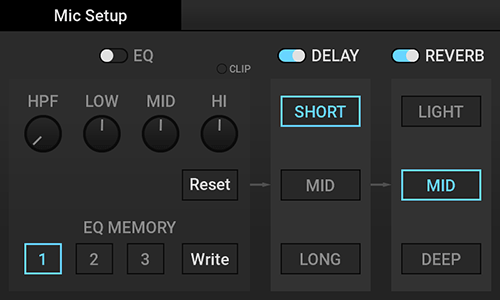
The "Mic Setup" screen is displayed. - Adjust the microphone input audio.
Item Description EQ Turns EQ on or off.
Touch each button to select, touch the knob to move up or down, or use the [DATA ENTRY] knob to adjust.- CLIP: Lights up red when clipping by setting the microphone input volume level or EQ.
- HPF: Adjusts the frequency of the high pass filter.
- LOW: Adjusts the low pitch sound.
- MID: Adjusts the middle pitch sound.
- HI: Adjusts the high pitch sound.
- Reset: Returns to the default.
- EQ MEMORY 1 to 3: Loads EQ presets saved in 1 to 3.
- Write: Press "Write" and then press any of the flashing EQ MEMORY "1" to "3" to save the current EQ settings to the pressed number. (If you press "Write" while "1" to "3" are blinking, the contents are reset without being saved.)
DELAY Turns DELAY on or off. - SHORT, MID, LONG: Adjust the Delay length.
REVERB Turns Reverb on or off. - LIGHT, MID, DEEP: Select the Reverb depth.
- Home
- Kaoss Pad function
- Home
- Kaoss Pad function
- Kaoss Pad mode
Kaoss Pad mode
If you press the [KAOSS PAD] button, the Touch Pad is set to Kaoss Pad mode.
- If the screen other than the Kaoss Pad is displayed, you cannot perform using the Kaoss Pad.
- The audio sound of the Kaoss Pad is always input from the Kaoss Pad's audio input system, the KAOSS FX Bus, and output to the Main Bus.
Signal flow
Hint
Kaoss Pad performance screen
Kaoss Pad mode has the following controls. You can use the [DATA ENTRY] knob to change Kaoss Pad Effects or BPM Out.

| Name | Function |
|---|---|
| 1. Kaoss Pad Effect | Activate using the [DATA ENTRY] knob to switch Kaoss Pad Effects
|
| 2. FX Release | Displays the enabled/disabled status of the FX Release function. The displayed content changes depending on the FX Release function of each Kaoss Pad Effect and the body settings. Kaoss Pad Effect List Setting the main unit |
| 3. FX Depth | Displays the setting value of the current FX Depth. Adjusting the effects |
| 4. Audio Clip Level | The Audio Clip information of the selected Trigger Pad is displayed. [BANK name] - [Pad number] are displayed on the top row, and Level on the bottom row. Activate with the [DATA ENTRY] knob to change the volume level of Audio Clip of the Target Pad. Also, if you press the Trigger Pad while holding down the Shift button, you can select the Trigger Pad without changing the playback/stop status. |
| 5. BPM Out | Use the [DATA ENTRY] knob to activate "BPM Out" and change the value. For some Kaoss Pad Effects, the effect synchronizes with tempo. Kaoss Pad Effect List Changing the tempo |
| 6. Touch playing part | Play while rubbing with your finger, tracing up, down, left, and right while touching, or tapping lightly. Operations are shown in red as traces. Hint You can also set your favorite image as the background image of the KAOSS PAD performance screen. Changing the background image Caution Do not use a hard or sharp object. The screen might not work correctly if you attempt to use it with a different object or while wearing gloves. |
- Home
- Kaoss Pad function
- Selecting the input source
Selecting the input source
Select the audio to input to the Kaoss Pad. The Kaoss Pad Effect is applied to the audio selected here.
- In Shift mode, press the [LINE/PHONO] button.
The "FX Target" screen is displayed. - Select the audio (Kaoss Pad Bus source) to input to the Kaoss Pad.
Press the audio button.- All the sources are selected by default.
- The unselected audios are sent to Dry Bus where the Kaoss Pad Effect does not work.
Signal flow - In Shift mode, press the [LINE/PHONO] button or the [KAOSS PAD] button to return to Kaoss Pad mode.
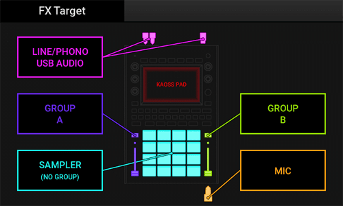
| FX Target | Audio source |
|---|---|
 | Audio of [LINE/PHONO IN] input or USB AUDIO |
 | Audio set to GROUP A Group setting |
 | Audio set to GROUP B Group setting |
 | Sampler audio (Audio not set to Group A or Group B) |
 | [MIC] input audio |
- Home
- Kaoss Pad function
- Adjusting the effects
Adjusting the effects
In Kaoss Pad mode, turn the [FX DEPTH] knob to adjust the effect depth.
- If you press one of the [HOT CUE/PROGRAM MEMORY] buttons 1 to 12 to load the memory contents, the value saved in memory is reflected regardless of the position of the [FX DEPTH] knob.
Hint
For details about the memory contents, refer to "Saving/loading the settings (Program Memory)".
- Home
- Kaoss Pad function
- Using Effects
Using Effects
In Kaoss Pad mode, operate the button to control the effect.
- Home
- Kaoss Pad function
- Using Effects
- Holding the effects (Touch Hold)
Holding the effects (Touch Hold)
Hold the effect status when you touch the Touch Pad.
- Press the [TOUCH HOLD] button, and release your hand from the Touch Pad.
The touching status is held at the position you touched last. Also, if you press the [TOUCH HOLD] button independently without touching the Touch Pad, the touching status is held at the position you touched last.- If you touch the Touch Pad again after releasing the Touch Pad, the touching status is held at the position where you newly touched.
- Pressing the [TOUCH HOLD] button again cancels the hold status.
- This function is enabled even in a mode other than Kaoss Pad mode (a trace is not displayed on the Touch Pad).
- When Program Memory is loaded, the touching status is held at the coordinates of the Program Memory.
- Home
- Kaoss Pad function
- Using Effects
- Recording the effects operation (Pad Motion)
Recording the effects operation (Pad Motion)
A motion of a Kaoss Pad Effect controlled using the Touch Pad is referred to as "Pad Motion".
You can record or play a Pad Motion to reproduce the same Effect operation at any time (the maximum recording time is about 12 seconds).
Recording a Pad Motion
- While holding down the [PAD MOTION] button, touch the Touch Pad.
A touch operation is recorded as a Pad Motion.- The [PAD MOTION] button flashes during recording.
- The previously recorded Pad Motions are erased.
- While the [PAD MOTION] button is pressed, operations are recorded, and a red trail is displayed when the Touch Pad is operated. When the recording ends after about 12 seconds, the red trail disappears.
- The hold status using the [TOUCH HOLD] button is not recorded.
- Pad Motion is not synchronized with BPM Out. Even if BPM is different between the recording and playback, the Pad Motion playback speed does not change.
- Release the [PAD MOTION] button.
The Pad Motion recording ends, and the recorded Pad Motion is played.
Playing back a Pad Motion
- Press the [PAD MOTION] button.
Pad Motion is played.- Press the [PAD MOTION] button again to stop.
- If you press the [PAD MOTION] button in Shift mode, the following operation is performed.
When Pad Motion is stopped: Reverse playback starts from the last recorded position.
When Pad Motion is playing: Reverse playback starts when the [PAD MOTION] button is pressed.
Hint
- If you touch the Touch Pad between pressing and releasing the [PAD MOTION] button, the Pad Motion is overwritten.
- When you record the "operation of releasing your finger from the Touch Pad" such as tapping the Touch Pad lightly as a Pad Motion, if you play while holding down the [TOUCH HOLD] button, the playback of the "operation of releasing your finger from the Touch Pad" changes to the playback of the "operation of holding down the Touch Pad without releasing your finger from the Touch Pad".
- Home
- Kaoss Pad function
- Saving/loading the settings (Program Memory)
Saving/loading the settings (Program Memory)
The Kaoss Pad mode settings can be saved or loaded as Program Memory.
Each of the 12 [PROGRAM MEMORY] buttons can be preset as a Kaoss Pad Program with the following settings.
Kaoss Pad Program
When you select and press one of the [PROGRAM MEMORY] buttons, the following settings saved in that button are loaded and reflected on Kaoss Pad operations.
- Kaoss Pad Effect
- FX Target setting
- FX Depth setting value
- Pad Motion
- [TOUCH HOLD] button on/off setting, and X (horizontal axis)/Y (vertical axis) coordinates
Current Kaoss Pad Program
The currently selected Kaoss Pad Program is referred to as the "Current Kaoss Pad Program".
Kaoss Pad Item
The data of 12 Kaoss Pad Programs is referred to as a "Kaoss Pad Item".
Kaoss Pad Items are saved in the built-in memory of the main unit. The settings can be saved even when the SD card is not inserted, and they are restored when the power is turned on again.
- When you press the [PROGRAM WRITE] button, data is saved in the built-in memory of the main unit. The Program Memory (Current Kaoss Pad Program) that was selected when the power was turned off is not automatically selected (restored).
- Kaoss Pad Item can be saved on the SD card as part of project data or loaded from the SD card together with project data.
- If you load a Kaoss Pad item from project data, the contents of the built-in memory of the main unit are overwritten with the Kaoss Pad item loaded from the SD card.
Saving
Save the Current Kaoss Pad Program to the [PROGRAM MEMORY] button.
- Press the [PROGRAM WRITE] button.
The [HOT CUE/PROGRAM MEMORY] buttons 1 to 12 flash.- If you press the [PROGRAM MEMORY] button again without pressing the [PROGRAM WRITE] button, save processing is canceled, and the [PROGRAM WRITE] button turns off.
- Press the [HOT CUE/PROGRAM MEMORY] button of the number you want to save
The Kaoss Pad Program is saved to the button number you pressed.
Hint
Loading
Hint
- Press any one of the [HOT CUE/PROGRAM MEMORY] buttons 1 to 12.
The contents are replaced with the ones of the Program Memory of the button you pressed.
- Home
- Sampler function
- Home
- Sampler function
- Sampler operation
Sampler operation
The sound that is played by pressing the Trigger Pad is referred to as an "audio clip".
An audio clip consists of two items: the data body of the sound to be played (audio clip data), and the attribute information (audio clip parameters).
Audio clip data
This unit can only handle WAV files of the following formats as audio clip data.
- WAV format (PCM Format)
- Stereo or Mono
- Quantization bit rate: 16 bits
- Sampling frequency: 48 kHz
- Play time: Within 30 minutes
Importing audio clips or WAV files
Audio clip
An audio clip consists of all or part of audio clip data (WAV file) only.
The WAV file has two points: "Start Point" that represents the elapsed time (Offset) from the head, and "End Point" that represents the end. The sound from this Start Point to the End Point is referred to as an "audio clip".
- Playback is performed in the range from the Start Point to the End Point, but not done in the part outside the range (gray part in the figure).
- A: Audio Clip Data (WAV file)
- B: Audio Clip
- C: Start Point
- D: End Point

Audio clip parameter
Attribute information specific for audio clip. This information is saved on the SD card with extension ".acp".
Audio clip parameters include "Start Point", "End Point", common parameters including "Play Mode" parameters, and parameters that are only available in a specific Play mode.
Play mode
The audio clip playback methods are as follows.
- One-way:
Playback starts from the Start Point and ends when the End Point is reached. Use this method when you want to play back only once. - Repeat:
Playback starts from the Start Point, and when it reaches the End Point, playback restarts from the Start Point. Use this method when you want to repeat playback. Playback is continually repeatedly until you press the Trigger Pad again to stop it.
Hint
| Playback method | Play mode | Repeat playback | Velocity | Operation |
|---|---|---|---|---|
| One-Way | 1-SHOT | Not performed | Enable | Playback starts from the Start Point and stops when the End Point is reached. You can change the volume up/down level with the strength by which you press the Trigger Pad (velocity). |
| SONG | Not performed | Disable | Playback starts from the Start Point and stops when the End Point is reached. Use this method for song data for one song that is longer than 1-SHOT or LOOP. | |
| Repeat | LOOP | Performed | Disable | Playback starts from the Start Point, and when it reaches the Loop Length, playback restarts from the Start Point. |
Simultaneous playback
Up to 16 audio clips can be played simultaneously.
If you try to play 16 or more, the candidates to be stopped are determined in the following priority order and stopped one by one. (For example, if the audio clip in item 1 is playing, it stops, and the audio clip in item 4 is played preferentially.)
- Audio clip under Monitoring
- Audio clip in 1-SHOT
- Audio clip in SONG
- Audio clip in LOOP
Hint
- For details about monitoring, refer to "Listening with headphones".
- When 16 audio clips are already playing in items 1 to 4, even if you try to play the Trigger Pad assigned to Monitoring in item 1, it will not play.
- If multiple candidates are provided for audio clips to stop playback, audio clips are stopped in order from the audio clip that played first.
- Home
- Sampler function
- Temporarily muting (Break)
Temporarily muting (Break)
If you execute the Break operation, the audio sound from the [LINE/PHONO IN] input and the playback sound of audio clips on all the Trigger Pads are temporarily muted.
- In Shift mode, press the [TOUCH HOLD] button.
While the [TOUCH HOLD] button is pressed, the Break operation is performed, and the input sound and playback sound are temporarily muted.- The [TOUCH HOLD] button flashes during the Break operation.
- Releasing the [TOUCH HOLD] button cancels the Break operation and returns to the original state.
- The audio sound from the [MIC] input is not muted.
- The reverberation of Delay or Reverb Effect on the Kaoss Pad is not muted (the effect that only leaves the reverberation will be obtained).
- Home
- Sampler function
- Setting the playback starting position (Hot Cue)
Setting the playback starting position (Hot Cue)
You can set any playback start position between the Start Point and End Point of an audio clip. This is referred to as "Hot Cue Point".
You can call the Hot Cue Point using one of the [HOT CUE] buttons 1 to 12 to play from that position immediately.

- A: Audio Clip Data (WAV file)
- B: Audio Clip
- C: Start Point
- D: End Point
- 1 to 3. Hot Cue Point
Hint
- For details about Audio File relationships, refer to "Sampler operation".
- Up to 12 Hot Cue Points can be set for each Trigger Pad.
- A Hot Cue Point can only be set for the Trigger Pad for which Play mode is set to "LOOP" or "SONG".
Hot Cue mode
Press the [HOT CUE] button to enter Hot Cue mode; the [HOT CUE/PROGRAM MEMORY] buttons (1 to 12) light up or turn off according to the following conditions.
Hot Cue button
Sets a hot cue to an audio clip on any Trigger Pad. When you press the Trigger Pad for playback, the [HOT CUE/PROGRAM MEMORY] button (1 to 12) lights up green or red, which indicates the following status.
| Button light on/off | Status |
|---|---|
| Lights up pale red. | No Hot Cue Point is set. |
| Lights up red. | Currently played while the Hot Cue Point is set: |
| Lights up green. | Currently stopped while the Hot Cue Point is set. |
The [HOT CUE/PROGRAM MEMORY] button (1 to 12) for which the Hot Cue Point is set is referred to as the "Hot Cue button".
Playing with Hot Cue
- Press the [HOT CUE] button.
The [HOT CUE] button lights, and Hot Cue mode turns on. - While holding down the [HOT CUE] button, press the Trigger Pad with a hot cue set.
The Hot Cue button that can be played lights up green. - Press any one of the Hot Cue buttons that are lit up green.
Playback starts from the Hot Cue Point set to that button (Hot Cue performance).- If a Trigger Pad is pressed while Hot Cue mode is turned on, playback starts from the Start Point in the same way as the usual Trigger Pad performance.
- If Play mode of the Hot Cue Target Pad is set to LOOP, playback starts from the Start Point after the Loop Length has been reached.
For details about Play mode, refer to "Play mode". For details about the Hot Cue Target Pad, refer to "Setting the Hot Cue target".
Ending the Hot Cue performance
- When Hot Cue mode is turned on, press the [HOT CUE] button.
Hot Cue mode exits.- The [HOT CUE/PROGRAM MEMORY] button (1 to 12) are set as the [PROGRAM MEMORY] button of Kaoss Pad mode.
- Home
- Sampler function
- Setting the playback starting position (Hot Cue)
- Setting the Hot Cue target
Setting the Hot Cue target
Select the Trigger Pad (Hot Cue Target Pad) you want to do a hot cue performance.
- While holding down the [HOT CUE] button, press the Trigger Pad.
The Trigger Pad you pressed is selected as a Hot Cue Target Pad.- The Hot Cue Target Pad lights up white.
- If only one Hot Cue Target Pad (Trigger Pad to which an audio clip is assigned) can be selected, it is selected automatically.
Hint
- If no Hot Cue Target Pads can be selected, the [HOT CUE] button turns off.
- When you press the [HOT CUE] button, the Hot Cue Target Pad you selected last is selected if you have previously selected a Hot Cue Target Pad.
- If no Hot Cue Target Pad has been selected, the [HOT CUE] button flashes, and a message is displayed to prompt you to select a Hot Cue Target Pad. If you press any Trigger Pad, it is selected as a Hot Cue Target Pad.
- Home
- Sampler function
- Setting the playback starting position (Hot Cue)
- Setting the Hot Cue Point
Setting the Hot Cue Point
Follow the steps below to make settings while playing a Hot Cue Target Pad.
For details about the Hot Cue Target Pad, refer to "Setting the Hot Cue target".
- While playing the Hot Cue Target Pad, press any one (the button that lights up pale red) of the [HOT CUE/PROGRAM MEMORY] buttons (1 to 12) you want to set the Hot Cue Point.
- Also, you can press any one of the "Hot Cue Point" (1 to 12) buttons for which the Hot Cue Point is not set on the screen to set a Hot Cue Point.
HOT CUE EDIT screen - The Hot Cue Point is set to the button you pressed. Hot Cue Points are not automatically sorted in the time series order of audio clip playback.
- When the Play Mode of the Hot Cue Target Pad is set to LOOP, Hot Cue Point can be set up to Loop Length.
- Also, you can press any one of the "Hot Cue Point" (1 to 12) buttons for which the Hot Cue Point is not set on the screen to set a Hot Cue Point.
- Home
- Sampler function
- Setting the playback starting position (Hot Cue)
- HOT CUE EDIT screen
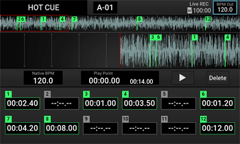
HOT CUE EDIT screen
If you press the [HOT CUE] button in Shift mode, the "HOT CUE EDIT" screen is displayed.
On this screen, you can adjust the playback position (Play Point) while checking waveforms of audio clip data (WAV file), and finely adjust the Hot Cue Point.
- 1
- 2
- 3
- 4
- 5
- 6
- 7
- 8
- 9
- Mode name
Displays the current mode name. - Trigger Pad No.
Displays the number of the Trigger Pad currently being edited. - BPM Out
Displays the BPM Out value. You can use the [DATA ENTRY] knob to change the value. - Waveform (Wide) pane
Displays waveforms of the entire audio clip data (WAV file).
Waveform (Wide) pane - Waveform (Zoom) pane
Displays the enlarged waveforms in the Waveform (Wide) pane for four seconds respectively before and after the "Play Point" in the longest case, which is eight seconds in total, focusing around the "Play Point" (the time of No. 7 in the figure).
Waveform (Zoom) pane - Native BPM
Displays Native BPM of the audio clip assigned to Hot Cue Target Pad (this value cannot be changed). - Play Point
The vertical line at the center of the Zoom area display is referred to as the "Play Point". In the stop state, playback starts from this position. During playback, this item indicates the position currently being played. Press "▶" (PLAY button) to play. - Delete button
Deletes Hot Cue Point (1 to 12).
Delete button - Hot Cue Point (1 to 12)
Displays the time of each Hot Cue Point.
Hot Cue Point (1 to 12)
Select the Trigger Pad (Hot Cue Target Pad) you want to do a hot cue edit.
- While holding down the [HOT CUE] button, press the Trigger Pad.
The Trigger Pad you pressed is selected as a Hot Cue Target Pad.
Waveform (Wide) pane
Displays waveforms from Start Point to End Point of the audio clip data set on the TRIGGER PAD EDIT screen.
If you press this while playback is in process or stopped, the Play Point moves to that position. You can drag the Play Point left or right to move it.

| Item | Description |
|---|---|
| 1. Waveform (Wide) | Displays waveforms of an audio clip. The waveforms on the left of the Play Point are displayed in a lighter color. |
| 2. Zoom area display | Indicates the range displayed in the Waveform (Zoom) pane with a red frame. |
| 3. Hot Cue Point | Displays the position of Hot Cue Point. |
Waveform (Zoom) pane
Enlarges the Zoom area of Waveform (Wide) waveforms. Displays the waveforms for four seconds respectively before and after the Play Point in the longest case, which is eight seconds in total, focusing around the Play Point.
To move the display range, drag the Play Point left or right on the pane while playback is in process or stopped.

| Item | Description |
|---|---|
| 1. Waveform (Zoom) | Enlarges the Zoom area of Waveform (Wide) waveforms. |
| 2. Play Point | Displays the Play Point (red vertical line) at the center. |
| 3. Hot Cue Point | Displays the position of Hot Cue Point. |
Delete button
Deletes Hot Cue Point (1 to 12).
- Press the "Delete" button.
The Hot Cue Point (1 to 12) corresponding to the Hot Cue Point on the screen flashes. - Press the time display box of one of the Hot Cue Points "1" to "12" to be deleted on the screen.
The selected Hot Cue Point is deleted.
Hot Cue Point (1 to 12)

When Hot Cue Point is set:
The time is displayed.
- If you press the Hot Cue Point, the Play Point moves to the currently set Hot Cue Point (in this case, the Hot Cue Point is not reconfigured).
- Playback starts from Hot Cue Point by pressing this part during playback. You can fine-adjust the position using the [DATA ENTRY] knob during playback. This fine adjustment also fine-adjusts the Play Point at the same time. If you play after making an adjustment in the stop state, playback starts from the position after adjustment.
When Hot Cue Point is not set:
"-- : -- . --" is shown in the display area.
- If you press the time display box with no value specified, the Hot Cue Point is set to the time at the current Play Point.
- Home
- Sampler function
- Setting the playback starting position (Hot Cue)
- Deleting the Hot Cue Point
Deleting the Hot Cue Point
Delete the set Hot Cue Point.
- In Shift mode, press the Hot Cue button you want to delete.
The Hot Cue Point of the button you pressed is deleted, and the button lights up pale red.
Hint
For details, refer to the "Delete button" on the "HOT CUE EDIT screen".
- Home
- Sampler function
- Setting the playback starting position (Hot Cue)
- Saving the Hot Cue Point
Saving the Hot Cue Point
The Hot Cue Point is saved per project as a project parameter.
To save the Hot Cue Point, save the project on the SD card (Save Project As).
- For details on how to save a project, refer to "Managing a project".
- If you turn off this unit, the projects and Hot Cue Points that are not saved are erased.
- Home
- Sampler function
- Sampling/Resampling
Sampling/Resampling
Recording the audio input to this unit and assigning it as an audio clip is referred to as "Sampling", and recording the audio output (Main Out) from this unit and assigning it as an audio clip is referred to as "Resampling".
In this operation description, Sampling is used; however, if you press the [SAMPLING] button in Shift mode, the operation is switched to Resampling.
- The maximum length of one Sampling/Resampling is 30 minutes.
- For Sampling/Resampling, you can listen to the metronome sound at the Reference Beat timing.
- The metronome sound is output to Monitor Bus, which can be listened to with headphones.
Monitoring the audio - Open the GLOBAL screen and set the metronome.
Hint
Relationship between Sampling and Resampling
| Function | Recorded audio |
|---|---|
| Sampling | Audio sound from [LINE/PHONO IN] input + USB Audio input + [MIC] input |
| Resampling | Audio sound from Main Out |
- For details about the audio system, refer to "Signal flow".
Sampling
Sample audio to any Trigger Pad. A Trigger Pad to be sampled is referred to as a "Sampling Target Pad".
- Press the [SAMPLING] button (for Resampling, press the [SAMPLING] button in Shift Mode).
A Trigger Pad without Audio Clip is initially selected as Sampling Target Pad, and the "Sampling Setting" ("Resampling Setting" for Resampling) screen is displayed.- The selected Sampling Target Pad flashes.
- If you press a Trigger Pad that does not flash, you can change Sampling Target Pad.
- If you press the [SAMPLING] button again without pressing the Sampling Target Pad, sampling is canceled, and the system returns to Kaoss Pad mode.
Hint- If no empty Trigger Pads are available in the selected TRIGGER PAD BANK, the [SAMPLING] button flashes, prompting you to select a Sampling Target Pad. When you press any Trigger Pad, it is selected as a Sampling Target Pad, and the "Sampling Setting" screen is displayed.
- Setting each item on the "Sampling Setting" screen
Item Description 1. Loop Length Set the loop length of the audio to be sampled.
The length can be selected from 1-SHOT, 1 beat to 64 beats, Free Beat, and Song.- You can operate the [DATA ENTRY] knob in Shift mode to select 1-SHOT, 1 beat to 16 beats (one beat increments), 20 beats to 64 beats (four beat increments), Free Beat, or Song.
- Selecting 1-SHOT sets to 1-SHOT Sampling, selecting 1 beat to 64 beats/Free Beat to Loop Sampling, and selecting Song to Song Sampling.
- If you stop sampling before reaching the specified number of 1-64 beats, or if you select Free Beat, Loop Sampling will automatically adjust to loop from the point where sampling stopped to the nearest beat.
- For LOOP sampling, set the Loop length here. The sampling length is determined by the BPM Out value and the Loop Length value at the start of sampling, so even if the BPM Out is changed during sampling, the change is not reflected in the sampling result.
2. Auto Trigger Sampling starts when the audio level of the audio to be sampled exceeds the threshold.
While the "Sampling Setting" screen is displayed, sampling is not started even if the indicator lights up red (lights up when the threshold is exceeded). Use this screen to determine whether the thresholds are appropriate.
The available thresholds are as follows- 0: -∞dBFS (Auto Trigger: Disable)
- 1 to 10: Approx. -42 dBFS to Approx. 0 dBFS (Auto Trigger enable)
NoteLower values are recommended for accurate sampling starts.3. Sampling Available Displays the remaining amount of time for sampling. If the SD card has sufficient free space for sampling for 30 or more minutes, "> 30 min" is displayed. - If the available sampling time is less than 30 minutes, the remaining amount of time is displayed.
4. Gate Set the Gate parameter before sampling, and it will be applied to the Audio Clip automatically at the end of the sampling process. - Press the Trigger Pad (Sampling Target Pad) again.
If Auto Trigger is set to 0 and Sampling Precount is set to off, Sampling starts immediately.
If the Sampling Precount is set to anything other than off, sampling will begin after the specified number of bars. At this time, you can set Metronome Level to a value other than 0 to monitor the metronome sound.
Setting the main unit
If Auto Trigger is set, sampling starts according to the set value.- If the Auto Trigger threshold is between 1 and 10, wait until the Auto Trigger conditions are satisfied. When the Auto Trigger conditions are satisfied, sampling starts.
- While sampling, the [SAMPLING] button blinks and the Sampling Target Pad lights up red.
- The Trigger Pads other than the Sampling Target Pad remain lit in the same way as in the normal Sampler mode, which enables you to operate a normal performance.
- Checking the sampling status
The following screen is displayed during sampling. Check the sampling status on this screen (the displayed screen varies depending on the Loop Length setting).- If the maximum time is reached during sampling or if the capacity of the SD card is insufficient, sampling is forcibly stopped and a message is displayed on the screen.
When Loop Length is set to "1-SHOT" or "Song":
1: Sampling elapsed time
When the Loop Length setting is "LOOP" (one beat to 64 beats):
1: Remaining sampling beat countLoop Length setting value Change in remaining beat count display 1 beat to 16 beats One square represents one beat. The indicator turns off one by one every time one beat passes. 20 beats to 64 beats One square represents four beats. The indicator turns off one by one every time four beats passes.
When Loop Length is set to "Free Beat":
1: Sampling progress bar <Bar.Beat>
Hint- If you press the [SAMPLING] button during sampling, sampling is canceled, and the system returns to the state before sampling started. (The sampled Audio File is not retained.)
- Ending sampling
When sampling ends, the [SAMPLING] button turns off, and Sampling mode ends. Tables 1 and 2 show the operation at the end of sampling and the parameters specified for audio clips, respectively.
Hint- If you press the Trigger Pad during Loop sampling, sampling is interrupted.
- For details about the setting for each parameter, refer to "TRIGGER PAD EDIT screen".
Table 1. Sampling end operation by Loop Length setting
Loop Length End of sampling Play mode set to a Trigger Pad 1-SHOT, Song If you press the Trigger Pad during sampling, it ends immediately. 1-SHOT, Song 1 beat to 64 beats, Free Beat If "Auto Play After Loop Sampling" is enabled in the Global settings, playback starts immediately as Loop Sample when recording is complete.
Setting the main unitLOOP Table 2. Parameters set at the end of sampling
Parameter Setting value Play mode 1-SHOT, LOOP, or SONG Start Point Sampling start position End Point Sampling end position Exclusive Assign OFF Link 1-SHOT or SONG: OFF
LOOP: ONNative BPM BPM Out value at start of sampling Loop Length 1-SHOT or SONG: 1 beat
LOOP: Loop Length sampledOffset 0 Level 100 Hot Cue Point All not set (1 to 12)


- Home
- Sampler function
- Sampling/Resampling
- Sampling using the Foot Switch
Sampling using the Foot Switch
Perform sampling using the Foot switch (optional).
Sampling operations using the Foot switch are only available when Foot SW mode is set to either Sampling or Resampling in the main unit settings.
Setting the main unit
Hint
- Press the Foot switch.
The "Foot SW Sampling Setting" screen ("Foot SW Resampling Setting" screen for Resampling) is displayed. The previous Sampling setting is displayed. Change the contents as needed.- When you press Foot Switch, an empty Trigger Pad is initially selected as the Sampling Target Pad (if “Foot SW Mode” in the main unit settings is set to “Sampling”).
Setting the main unit - You can select the [DATA ENTRY] knob or Trigger Pad to select Sampling Target Pad.
- The selected Sampling Target Pad flashes red (Trigger Pads other than the selected one are indicated in the normal Sampler mode).
- When you press Foot Switch, an empty Trigger Pad is initially selected as the Sampling Target Pad (if “Foot SW Mode” in the main unit settings is set to “Sampling”).
- Press the Foot switch again.
Sampling starts.- When sampling starts, the "Foot SW Sampling Mode" screen closes.
- For LOOP Sampling, if "Auto Play After Loop Sampling" is enabled in the Global settings, playback starts as Loop Sample immediately after Loop Sampling ends.
Setting the main unit
Also, if you press the Foot Switch before reaching the Free Beat setting or the specified number of beats, the Loop is sampled with the number of beats from the time you press the switch to the nearest beat position. - For 1-SHOT or SONG sampling, press the Foot Switch at any timing to end sampling.
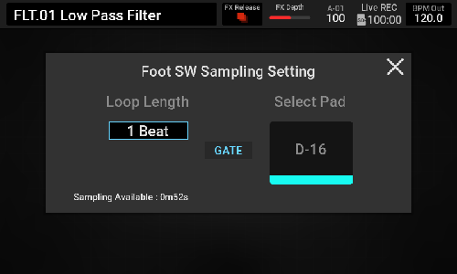
- Home
- Setting an audio clip
Setting an audio clip
Set an audio clip on the Trigger Pad. A Trigger Pad to be set is referred to as an "Edit Target Pad".
- Press the [TRIGGER PAD EDIT] button.
The last Trigger Pad you pressed is selected as the Edit Target Pad and the "TRIGGER PAD EDIT" screen is displayed.- The selected Edit Target Pad lights up white.
- If you press the [TRIGGER PAD EDIT] button again, the system cancels the Audio Clip setting on the Trigger Pad, and returns to Kaoss Pad mode.
Hint
- If no Edit Target Pad can be selected, the [TRIGGER PAD EDIT] button is not lit up.
- If no Edit Target Pad has been selected for any reason, the [TRIGGER PAD EDIT] button flashes, and a message is displayed to prompt you to select an Edit Target Pad. If you press any Trigger Pad with Audio Clip, it is selected as an Edit Target Pad, and the "TRIGGER PAD EDIT" screen is displayed.
- Home
- Setting an audio clip
- TRIGGER PAD EDIT screen
TRIGGER PAD EDIT screen
Set an audio clip.
The three types of screens are provided depending on Play mode of the audio clip.
When Play mode is set to LOOP:
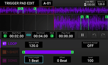
- 1
- 2
- 3
- 4
- 5
- 6
- 7
- 8
- 9
- 10
- 11
- 12
- Mode name
Displays the current mode name. - Trigger Pad name
Displays [BANK name] - [Pad number]. - BPM Out
Displays the BPM Out value. You can use the [DATA ENTRY] knob to change the value. - Waveform (Wide) pane
Displays waveforms of the entire audio clip data (WAV file).
Waveform (Wide) pane - Waveform (Zoom) pane
Displays the enlarged waveforms in the Waveform (Wide) pane for four seconds respectively before and after the "Play Point", which is a maximum of eight seconds in total, focusing around the "Play Point" (the time of No. 9 in the figure).
Waveform (Zoom) pane - Start Point pane
Displays the time at the "Start Point" position of an Edit Target Pad.
Start Point pane - Link button
When Link is set to ON (light blue), the length between the "Start Point" and the "End Point" is fixed. If the "Start Point" is changed, the "End Point" is also changed. Even if you change the "End Point", the "Start Point" moves synchronously.
When Link is set to OFF (gray), the "Start Point" and the "End Point" are not synchronized, and the settings can be changed individually. - End Point pane
Displays the time at the "End Point" position of an Edit Target Pad.
End Point pane - Play Point
The vertical line at the center of the Waveform (Zoom) pane is referred to as the "Play Point".
In the stop state, playback starts from this position. During playback, this item indicates the position currently being played. Press "▶" (PLAY button) to start playback.
Play Point pane - Play button
Perform the playback or stop operation. - Undo/Redo button
Perform operations to return to the state before settings were changed (Undo) and to return to the state before Undo was executed (after changing settings) (Redo). - Setting pane specific to Play mode
Change Play mode or set the detail.
Play Mode pane
When Play mode is set to 1-SHOT:
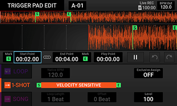
When Play mode is set to SONG:
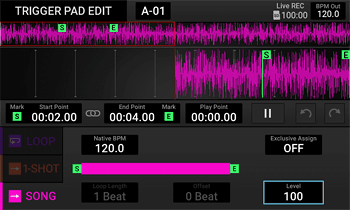
- Home
- Setting an audio clip
- TRIGGER PAD EDIT screen
- Waveform (Wide) pane
Waveform (Wide) pane
This pane displays waveforms of the entire audio clip.
If you press this while playback is in process or stopped, the Play Point moves to that position. You can drag the Play Point left or right to move it.

| Item | Description |
|---|---|
| 1. Waveform (Wide) | Displays waveforms of an audio clip. The waveforms on the left of the Play Point are displayed in a darker color. |
| 2. Zoom area display | Indicates the range displayed in the Waveform (Zoom) pane with a red frame. |
| 3. Start Point | Position of Start Point |
| 4. Loop Point | The Loop Point position is displayed according to the Loop Length setting (displayed only when Play Mode is set to Loop). |
| 5. End Point | Position of End Point |
- Home
- Setting an audio clip
- TRIGGER PAD EDIT screen
- Waveform (Zoom) pane
Waveform (Zoom) pane
Enlarges the Zoom area of Waveform (Wide) waveforms. Displays the waveforms for four seconds respectively before and after the Play Point, which is a maximum of eight seconds in total, focusing around the Play Point.
To move the display range, drag the Play Point left or right on the pane while playback is in process or stopped.

| Item | Description |
|---|---|
| 1. Waveform (Zoom) | Enlarges the Zoom area of Waveform (Wide) waveforms. |
| 2. Play Point | Displays the Play Point (red vertical line) at the center. |
| 3. Start Point | Only displayed when the Start Point is specified in the Zoom range. |
| 4. End Point | Only displayed when the End Point is specified in the Zoom range. |
- Home
- Setting an audio clip
- TRIGGER PAD EDIT screen
- Start Point pane
Start Point pane
Displays the time at the "Start Point" position of an Edit Target Pad.

| Item | Description |
|---|---|
| 1. Mark "S" button | Press this button to reset the position (time) at the current Play Point as the "Start Point". |
| 2. Start Point time display | Press the time display area of the Start Point to move to the "Start Point" to which the Play Point is currently set.
|
- Home
- Setting an audio clip
- TRIGGER PAD EDIT screen
- End Point pane
End Point pane
Displays the time at the "End Point" position of an Edit Target Pad.

| Item | Description |
|---|---|
| 1. End Point time display | Press the time display area of the End Point to move to the "End Point" to which the Play Point is currently set.
|
| 2. Mark "E" button | Press this button to reset the position (time) at the current Play Point as the "End Point". |
- Home
- Setting an audio clip
- TRIGGER PAD EDIT screen
- Play Point pane
Play Point pane
Perform the playback or stop operation, or display and adjust the time at the Play Point.

| Item | Description |
|---|---|
| 1. Play Point time display | Displays the time at the Play Point. The time is displayed as the actual time set before Time Stretch, regardless of the BPM Out setting value.
|
| 2. "▶" (Play button) | Perform the playback or stop operation. |
- Home
- Setting an audio clip
- TRIGGER PAD EDIT screen
- Play Mode pane
Play Mode pane
Set Play mode of an Edit Target Pad.
When the "TRIGGER PAD EDIT" screen opens, the Play mode tab set in the Edit Target Pad is selected.
Hint

| Item | Description |
|---|---|
| 1. Native BPM | Change the Native BPM value of the audio clip assigned to the Edit Target Pad (the value cannot be changed when Play mode is set to 1-SHOT). Press "Native BPM" and change the setting using the [DATA ENTRY] knob.
|
| 2. Exclusive Assign | Set the Exclusive Assign number of the Edit Target Pad. By setting the same Exclusive Assign number for different Trigger Pads, you can only play the Trigger Pad you pressed later when trying to play Trigger Pads with the same Exclusive Assign number at the same time. Press "Exclusive Assign" and change the setting using the [DATA ENTRY] knob.
|
| 3. Loop Length | Set the loop length. Press "Loop Length" and change the setting using the [DATA ENTRY] knob. For details, refer to "Loop Length". |
| 4. Offset | Change the sound generation starting position of an audio clip (the position cannot be changed when Play mode is set to 1-SHOT or SONG). For details, refer to "Offset". |
| 5. Level | Set the volume level of the audio clip on the Edit Target Pad. Press "Level" and change the setting using the [DATA ENTRY] knob.
|
Loop Length
Set the loop length.
If you set "Loop Length" to 4Beat for the audio clip sampled with LOOP when sampling as shown in Figure 1, the audio clip changes to the 4-beat audio data, and the settings match between "Loop Length" and "Start Point" to " End Point".
- The available setting range is "1Beat" to "16Beat" (in steps of 1Beat) and "20Beat" to "64Beat" (in steps of 4Beat). If it is set in Shift mode, you can select the desired one from all setting values.
- If Link is set to ON, "Loop Length" cannot be changed.
- A = Audio Clip Data (WAV file)
- B = Audio Clip
- C = Start Point
- D = End Point
- E = Loop Length
- F = Silent Part
• Figure 1 Loop Length = 4Beat

• Figure 2 Loop Length = 2Beat

- When the "Loop Length" is changed to 2Beat, if the audio clip reaches halfway point (two beats) as shown in Figure 2, control returns to the "Start Point" to loop a performance (only the first two beats of the audio clip are looped).
• Figure 3 Loop Length = 8Beat

- When the "Loop Length" is changed to 8Beat, the section from "End Point" to the end of the WAV File becomes silent after the 4-beat audio clip was played as shown in Figure 3, control returns to the "Start Point" after the 4-beat silent interval (F) including that interval.
Offset
Change the sound generation starting position of an audio clip.
As an example, if you change Play mode of the audio clip sampled with 1-SHOT to LOOP (Figure 1) and reset the "Loop Length" to 4Beat (Figure 2), 1-SHOT is played once every four beats.
- "Loop Length" is set to 0Beat immediately after sampling. The setting value depends on the "Loop Length" value, which can be set from 0 to ("Loop Length"-1) Beat.
- A = Audio Clip Data (WAV file)
- B = Audio Clip
- C = Start Point
- D = End Point
- E = Loop Length
• Figure 1 Sample with 1-SHOT changed to LOOP (Loop Length = 1)

• Figure 2 Change to Loop Length = 4Beat (Offset = 0Beat)

If you want to sound this 1-SHOT on the fourth beat of 4/4, set "Offset" to 3Beat (Figure 3); playback starts at the fourth beat.
• Figure 3 Offset = 3Beat (Loop Length = 4)

- If "Offset" is set to 1Beat in Figure 3, playback is performed at the second beat. If "Offset" is set to 2Beat, playback is performed at the third beat.
- Home
- Setting an audio clip
- Trimming an audio clip
Trimming an audio clip
The operation of recreating audio clip data to the minimum required size is referred to as "Trimming".
Extract a part of an audio clip to use it as a 1-SHOT or LOOP audio clip or use a part of LOOP as 1-SHOT.
Extracting an audio clip enables you to delete unnecessary parts and save space on the SD card.
- When trimming is performed, audio data between "Start Point" and "End Point" of audio clip data (WAV File) is extracted.
Start Point pane
End Point pane - To execute trimming, specify options when executing "Copy Audio Clip" to copy an audio clip and executing "Project Save As" to save a project.
Copying an audio clip
Managing a project
- Home
- Setting an audio clip
- Setting the Trigger Pad assignment
Setting the Trigger Pad assignment
Copy, move, or replace an audio clip assigned to a Trigger Pad to another Trigger Pad, or delete an assigned audio clip.
- In Shift mode, press the [TRIGGER PAD EDIT] button.
The "TRIGGER PAD UTILITY" screen is displayed.
HintWhen you select a function on this screen, all Sampler playback operations stop, and Mute, Solo, Variable Pitch, and Monitoring settings of all the Trigger Pads are turned off (the Group Monitoring on/off setting remains unchanged). - Press the button you want to set.
Item Description COPY Copies the contents of the Trigger Pad to another Trigger Pad.
Copying an audio clipMOVE Moves the contents of the Trigger Pad to another Trigger Pad.
Moving an audio clipSWAP Swaps the contents of the Trigger Pad with the contents of another Trigger Pad.
Swapping an audio clipDELETE Deletes the contents of the Trigger Pad.
Deleting an audio clipIMPORT Imports an audio clip on the Trigger Pad.
Importing audio clips or WAV files
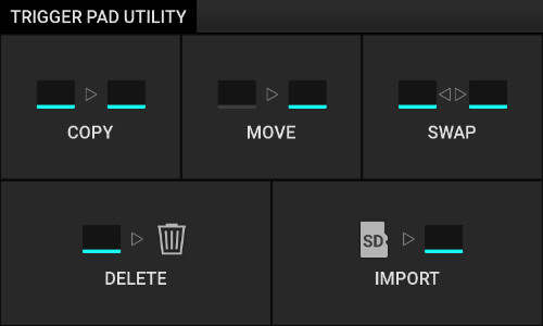
- Home
- Setting an audio clip
- Setting the Trigger Pad assignment
- Copying an audio clip
Copying an audio clip
Copy the contents of the Trigger Pad to another Trigger Pad.
- Press "COPY" on the "TRIGGER PAD UTILITY" screen.
The "Copy Audio Clip" screen is displayed. - Select "Source" (a Trigger Pad used as the copy source).
Turn the [DATA ENTRY] knob or press the Trigger Pad to select the source.- If you press the Trigger Pad, the audio clip on that Trigger Pad is played, and the "Source" display changes to the selected Trigger Pad name.
- Press the "x" button to cancel and return to the "TRIGGER PAD UTILITY" screen.
- Select "Destination" (Trigger Pad used as the copy destination).
Activate "Destination" using the [DATA ENTRY] knob, or press the "Destination" display area. While "Destination" is selected, use the [DATA ENTRY] knob to select the Trigger Pad used as the copy destination.- If you select a Trigger Pad assigned to an audio clip, the audio clip on the Trigger Pad is played.
- If you press "
(When Trimming is set) - Press "OK".
The contents of the Trigger Pad set to the "Source" are copied to the Trigger Pad set to the "Destination".- When the procedure has been completed, the display returns to the "TRIGGER PAD UTILITY" screen.
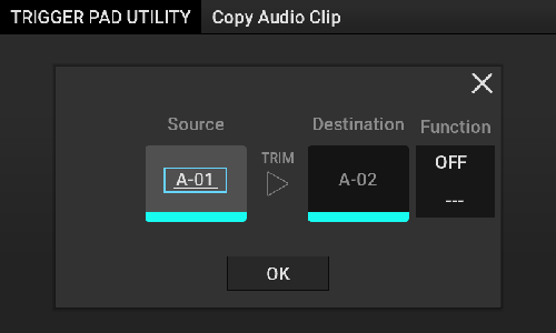
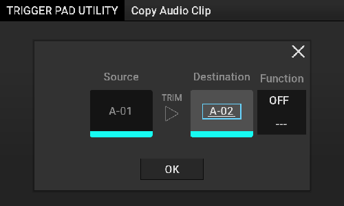
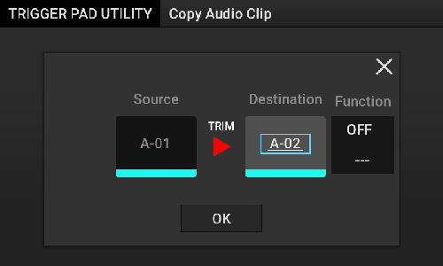
Adjusting the waveform to the maximum level without distortion
Use the [DATA ENTRY] knob to change the Function item to "NORMZ".
If you copy in this state, the Audio Clip Data (WAV File) on the “Destination” side is converted to the maximum level without a waveform distortion.
Changing the pitch of the waveform
Use the [DATA ENTRY] knob to change the Function item to "PITCH".
The integer part of the numerical values in the lower row is in semitones. If Copy is carried out while the "PITCH" value is changed to a value other than 0.00, the waveform pitch is converted for the Audio Clip Data (WAV File) on the "Destination" side. Turning the [DATA ENTRY] knob in Shift Mode increases or decreases the waveform pitch by 0.01.
Note
Converting the waveform to reverse playback
Use the [DATA ENTRY] knob to change the Function item to "REVRS".
If you copy while it is in this state, the Audio Clip Data (WAV File) on the “Destination” side is converted so that the waveform is played in reverse.
- Home
- Setting an audio clip
- Setting the Trigger Pad assignment
- Moving an audio clip
Moving an audio clip
Move the contents of the Trigger Pad to another Trigger Pad.
- Press "MOVE" on the "TRIGGER PAD UTILITY" screen.
The "Move Audio Clip" screen is displayed.- For details about how to set "Source" and "Destination", refer to "Copying an audio clip".
- Press "OK".
The contents of the Trigger Pad set to the "Source" are moved to the Trigger Pad set to the "Destination".- When the procedure has been completed, the display returns to the "TRIGGER PAD UTILITY" screen.
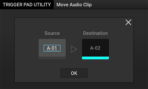
- Home
- Setting an audio clip
- Setting the Trigger Pad assignment
- Swapping an audio clip
Swapping an audio clip
Swap the contents of the Trigger Pad with another Trigger Pad.
- Press "SWAP" on the "TRIGGER PAD UTILITY" screen.
The "Swap Audio Clip" screen is displayed.- For details about how to set "Source" and "Destination", refer to "Copying an audio clip".
- Press "OK".
The contents of the Trigger Pad set to the "Source" are swapped with the Trigger Pad set to the "Destination".- When the procedure has been completed, the display returns to the "TRIGGER PAD UTILITY" screen.
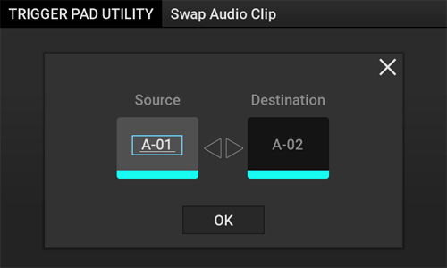
- Home
- Setting an audio clip
- Setting the Trigger Pad assignment
- Deleting an audio clip
Deleting an audio clip
Delete the contents of the Trigger Pad.
- Press "DELETE" on the "TRIGGER PAD UTILITY" screen.
The "Delete Audio Clip" screen is displayed. - Select a Trigger Pad to delete an audio clip from.
Use the [DATA ENTRY] knob to select a Trigger Pad.- Press the "x" button to cancel and return to the "TRIGGER PAD UTILITY" screen.
- Press "Delete".
The contents of the selected Trigger Pad are deleted.- When the procedure has been completed, the display returns to the "TRIGGER PAD UTILITY" screen.
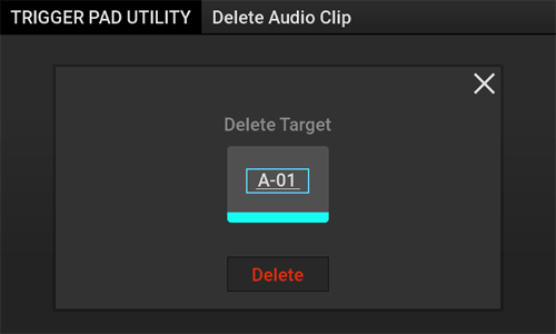
- Home
- Setting an audio clip
- Setting the Trigger Pad assignment
- Importing audio clips or WAV files
Importing audio clips or WAV files
Import audio clips or WAV files to Trigger Pads.
- Press "IMPORT" on the "TRIGGER PAD UTILITY" screen.
The "Import Audio Clip" screen is displayed.
HintUp to 128 WAV files can be displayed in each folder. - Select the file to be imported.
Use the [DATA ENTRY] knob to select the desired one.- ▶Folder name: Moves into the specified folder.
- ▶..: Returns to the previous (upper) folder.
- Press the "▶" (Play button) on the right of the file name to play the audio clip (if you press "▶" (Play button) while holding down the [MONITOR] button, sound is output to headphones only).
- You can select the following audio clips or WAV files on the SD card to import them.
- Folder: Root, "Live Rec", "Kaoss Replay Projects", "Import"
- File: 44.1 kHz or 48 kHz, 16bit or 24bit, playback time within 30 minutes
- Setting BPM
Set the BPM value of an audio clip using the [DATA ENTRY] knob.- If you press "Auto" to display in blue, the BPM value is automatically detected and set when importing (if it could not be detected automatically, BPM is set to 120.0).
To manually set the BPM value, press "Auto" to cancel the automatic detection (changes to gray), and then set the BPM value using the [DATA ENTRY] knob. Turning the [DATA ENTRY] knob in Shift mode increases or decreases the value in 0.1 BPM increments.
- If you press "Auto" to display in blue, the BPM value is automatically detected and set when importing (if it could not be detected automatically, BPM is set to 120.0).
- Selecting the Trigger Pad used as the "Destination" (import destination)
Set "Destination" using the [DATA ENTRY] knob. - Selecting "Play Mode" from 1-SHOT, LOOP, and SONG
Use the [DATA ENTRY] knob to set "Play Mode". - Selecting "GATE" OFF/ON.
If you press "GATE" to change to the blue display, GATE MODE is set to ON. - Press "OK".
The selected audio clip is set to the Trigger Pad used as the "Destination".- When the procedure has been completed, the display returns to the "Import Audio Clip" screen.
- If "Auto" is enabled (blue), it takes longer to complete the procedure.
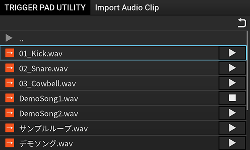
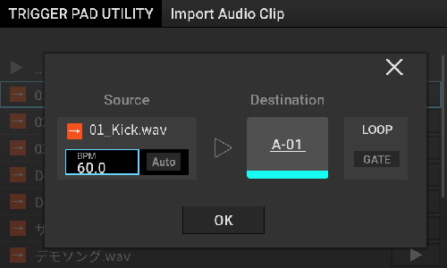
- Home
- Group setting
Group setting
You can assign the audio sound of the Trigger Pad output or [LINE/PHONO IN] input to the fader of GROUP A or B, and adjust the volume level for each group as a whole. You can also select whether or not to input to a Kaoss Pad Effect for each group.
Hint
- This function is available for a turntable scratch play using the fader by assigning the [LINE/PHONO IN] input.
- The group settings are saved per project as project parameters. To save the group settings, save the project on an SD card.
Managing a project
- Home
- Group setting
- Assigning the source
Assigning the source
Assign the source to a group.
- While holding down the button ([GROUP A] or [GROUP B] button) of the group to be assigned, press the Trigger Pad you want to use as the source or the [LINE/PHONO] button.
The Trigger Pad or button you pressed is selected as the audio source and assigned to GROUP A or B.- The Trigger Pad or button of the selected source flashes. If you press the source again while source is flashing, the Trigger Pad or button turns off, and the group assignment is deselected.
- The group assignment can be selected even while the Trigger Pad is playing.
- You can combine and select multiple Trigger Pads and buttons. You can also select across Trigger Pad Bank.
- Even if you press a Trigger Pad while selecting a group, it is not played.
- Home
- Group setting
- Audio output at group setting
Audio output at group setting
When a group is set, the input and output of audio are as follows.
The audio level of the group can be adjusted using the fader of [GROUP A] or [GROUP B].
- The amount of fader change can be changed with the “Group Fader Curve” in the main unit settings.
Setting the main unit - For details about the audio input/output system, refer to "Signal flow".
| Select GROUP A. | Select GROUP B. | Audio output destination |
|---|---|---|
| - | - | Trigger Pad output sound: Sampler Bus [LINE/PHONO IN] input sound: Kaoss Pad Bus or Dry Bus (depends on the FX Target setting.) Selecting the input source |
| 〇 | - | Input section of group fader A |
| - | 〇 | Input section of group fader B |
| 〇 | 〇 | Input section of group fader A and group fader B |
- Home
- Group setting
- Canceling the group setting
Canceling the group setting
Reset the group settings.
- In Shift mode, press the [GROUP A] button or the [GROUP B] button.
All the sources assigned to GROUP A or GROUP B are unassigned.- The audio output destination is set to Sampler Bus.
Signal flow
- The audio output destination is set to Sampler Bus.
- Home
- Monitoring the audio
Monitoring the audio
While multiple Trigger Pads are sounding, you can only listen to the audio of the selected monitor target (Monitor Bus) through headphones.
- The Monitor Bus audio does not pass through the Kaoss Pad, so the Kaoss Pad Effect is not reflected.
- You can adjust the volume balance between the Main Bus and Monitor Bus using the [MONITOR MIX] knob.
- For details about the audio input/output system, refer to "Signal flow".
| Monitoring target | Specification method |
|---|---|
| Playback sound of each Trigger Pad | While holding down the [MONITOR] button, press the Trigger Pad to specify. |
| Output sound of the Pre Fader system in GROUP A or GROUP B | While holding down the [MONITOR] button, press the [GROUP A] or [GROUP B] button to specify. |
- While holding down the [MONITOR] button, press the Trigger Pad or the button of the group you want to monitor.
The system enters Monitor Selection mode, and the Trigger Pad or the button of the group to be monitored flashes.- To turn off the group monitoring, deselect the group in Monitor Selection mode, or perform the All Monitor OFF operation.
Canceling Monitor settings
- To turn off the group monitoring, deselect the group in Monitor Selection mode, or perform the All Monitor OFF operation.
- Home
- Monitoring the audio
- Listening with headphones
Listening with headphones
You can output the Trigger Pad output to the Monitor Bus only to listen with headphones.
- Press any of the Trigger Pads in Monitor Selection mode.
The Trigger Pad you pressed is targeted for Monitoring. When it is played, audio is output to the Monitor Bus only.
Signal flow- For details about Monitor Selection mode, refer to "Monitoring the audio".
- The Trigger Pad being monitored flashes white.
- The Trigger Pad audio is not output to the Sampler Bus during monitoring.
- When you press the Trigger Pad with Monitoring set, it is played from the Start Point (only output to the Monitor Bus, not to the Sampler Bus).
- A Trigger Pad to which no audio clip is assigned cannot be set.
Hint
For details, refer to "Simultaneous playback" in "Sampler operation".
- Home
- Monitoring the audio
- Canceling Monitor settings
Canceling Monitor settings
Cancel the Monitor settings.
- In Shift mode, press the [MONITOR] button.
The Monitoring setting of all the Trigger Pads or the Group Monitoring settings in GROUP A or B is canceled, and Monitor Selection mode turns off (All Monitor OFF operation).
- Home
- Managing data on an SD card
Managing data on an SD card
Manage data on an SD card.
Note

- Home
- Managing data on an SD card
- CARD screen
CARD screen
This is the screen for managing the SD card.
- Press the [CARD] button.
The "CARD" screen is displayed.- If no SD card is inserted, the "CARD" screen is not displayed.
- If you press the [CARD] button while playing to select each function, a message is displayed to notify that playback is stopped. Press "x" to return to the original screen without stopping playback.
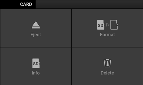
| Item | Description |
|---|---|
| Eject | Eject the SD card. Ejecting the SD card |
| Format | Initialize the SD card so that it can be used with this unit. (This option cannot be selected if an SD card other than a microSD card or microSDHC card is inserted. Formatting the SD card |
| Info | Displays the amount of available storage space and the total capacity of the SD card. |
| Delete | Deletes the contents of the SD card. Deleting a file |
- Home
- Managing data on an SD card
- Ejecting the SD card
Ejecting the SD card
Eject the SD card from this unit.
- Press "Eject" on the "CARD" screen.
The "Eject SD Card" screen is displayed. - Checking the message
Press "Eject" to eject the SD card.- If some editing contents have not been saved in Current Project, a message is displayed to notify you that some editing contents have not been saved.
If you press "YES", the SD card is ejected without saving the editing contents that have not been saved.
Press "x" to return to the "CARD" screen.
Saving a project
- If some editing contents have not been saved in Current Project, a message is displayed to notify you that some editing contents have not been saved.
- Eject the SD card.
When the following screen is displayed, eject the SD card.- When the SD card is ejected, the system returns to Kaoss Pad mode.
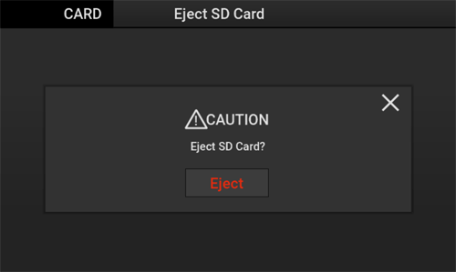
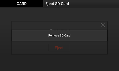
Hint
- Home
- Managing data on an SD card
- Formatting the SD card
Formatting the SD card
Format the SD card so that it can be used with this unit.
Note
- Press "Format " on the "CARD" screen.
The "Format SD Card" screen is displayed.- Press "x" to return to the original screen without formatting the SD card.
- Press "Format".
Format the SD card.- At this time, the projects that are not saved are also discarded.
- Checking the message
When formatting has been completed, the system returns to Kaoss Pad mode.
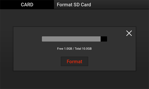
- Home
- Managing data on an SD card
- Deleting a file
Deleting a file
Delete the files on the SD card.
- The files in the "Kaoss Replay Projects" folder cannot be deleted from this menu.
- Press "Delete" on the "CARD" screen.
The "Delete File" screen is displayed. - Select the file to be deleted.
Press File or select the desired file using the [DATA ENTRY] knob. - Press "Delete".
Delete the selected file.- When file deletion has been completed, the display returns to the "Delete File" screen.
- Press "x" to return to the "Delete File" screen without deleting any files.
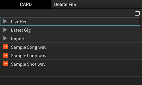
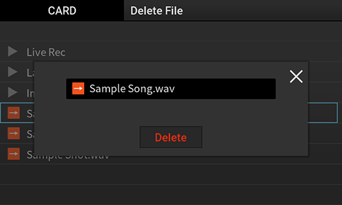
- Home
- Managing a project
Managing a project
A project is a collection of the following information assigned to a Trigger Pad. This information is managed as one project.
- Audio clip (max. 128 items)
- Hot Cue Point
- Kaoss Pad Program Memory
Hint
- Multiple projects can be saved on the SD card.
- If there is not enough available storage space on the SD card, it may not be able to hold 128 audio clips. Delete unnecessary files to increase the amount of available storage space on the SD card.
Deleting a file
Deleting a project
- Home
- Managing a project
- PROJECT screen
PROJECT screen
This screen is used to manage projects.
- Press the [PROJECT] button.
The "PROJECT" screen is displayed.- If some editing contents have not been saved in Current Project when a project is operated, a message is displayed to ask whether to discard the Current Project that is not saved.
- If "x" is selected for the message, the "Save Project As" screen is displayed to enable you to save the project. You can carry out project operation after the Save Project As step.
- If "OK" is selected for the message, the contents of Current Project are discarded and the project will be operated.
- If some editing contents have not been saved in Current Project when a project is operated, a message is displayed to ask whether to discard the Current Project that is not saved.
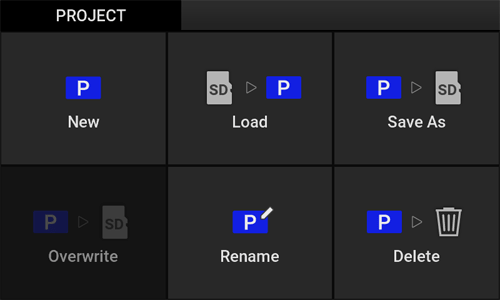
| Item | Description |
|---|---|
| New | Initializes the contents of Current Project and creates a new project. Creating a project |
| Load | Loads projects onto the SD card. Loading a project |
| Save As | Names the Current Project and saves it on the SD card. Saving a project |
| Rename | Renames the project data on the SD card. Renaming a project |
| Delete | Deletes the project data on the SD card. Deleting a project |
| Overwrite | Overwrites the Current Project on the SD card without renaming it. (If the Current Project cannot be overwritten, it is grayed out.) |
- Home
- Managing a project
- Creating a project
Creating a project
Create a new project. The Current Project (current contents) are initialized.
To save the Current Project, refer to "Saving a project".
- Press "New" on the "PROJECT" screen.
A new project is created.- The message "New project has been created" is displayed.
- After a project was created, the display returns to the original screen.
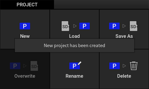
- Home
- Managing a project
- Loading a project
Loading a project
Load an existing project.
- Press "Load" on the "PROJECT" screen.
The "Load Project" screen is displayed. - Select a project to load.
Press the displayed project name, or select the project using the [DATA ENTRY] knob. The project is loaded, and the display returns to the original screen.
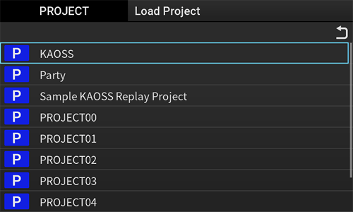
- Home
- Managing a project
- Saving a project
Saving a project
Save the Current Project.
- Press "Save As" on the "PROJECT" screen.
The "Save Project As" screen is displayed.- Press "x" to return to the "PROJECT" screen without saving the Current Project.
- Enter the project name.
When you press the button on the keyboard section, text is entered in the light blue area.- If you press the "Auto" button without entering anything in the project name field, a project name from 00 to 99 is entered automatically.
- If a project with the same name exists, a message is displayed to confirm whether to overwrite the project. You can press "OK" to overwrite the project, or you can press “×” to reset the project name without overwriting the project.
- Select an option.
The "Options" screen is displayed. Set the items to save and select whether to perform Trimming.Item Description Microphone setup
(Selected by default.)Saves the contents of the microphone setup. Kaoss Pad
(Selected by default.)Saves the contents of Kaoss Pad Item. Trimming Performs Trimming based on the Start Point and End Point specified in Trigger Pad Edit and saves the result.
Trimming an audio clip - Press "OK".
To save the project, set the option, and press "OK".- After saving, the display returns to the "PROJECT" screen.
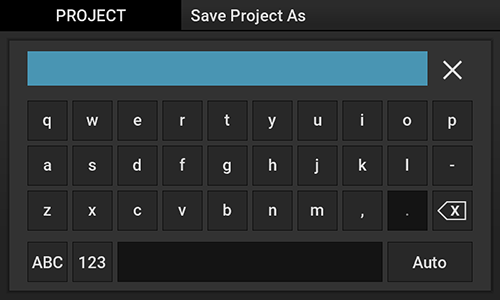
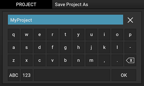
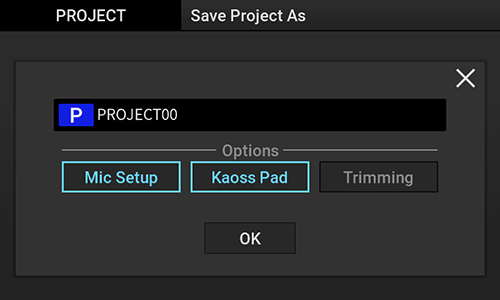
- Home
- Managing a project
- Renaming a project
Renaming a project
Rename an existing project.
- Press "Rename" on the "PROJECT" screen.
The "Rename Project" screen is displayed. - Select a project to rename.
Press the project, or select the project using the [DATA ENTRY] knob. - Enter the project name.
When you press the button on the keyboard section, text is entered in the light blue area.- If you press the "Auto" button without entering anything in the project name field, a project from 00 to 99 is entered automatically.
- If a project with the same name exists, a message is displayed to confirm whether to overwrite the project. You can press "OK" to overwrite the project, or you can press "CANCEL" to return to the text entry state without overwriting the project.
- Press "x" to return to the "PROJECT" screen without renaming the project.
- Press "OK".
The project is renamed.- After the renaming process is complete, the display returns to the "PROJECT" screen.
- Home
- Managing a project
- Deleting a project
Deleting a project
Delete an existing project.
- Press "Delete" on the "PROJECT" screen.
The "Delete Project" screen is displayed. - Select a project to delete.
Press the project, or select the project using the [DATA ENTRY] knob. - Press "Delete".
The project is deleted.- After the project is deleted, the display returns to the "PROJECT" screen.
- Press "x" to return to the previous screen without deleting the project.

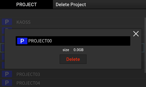
- Home
- Setting the main unit
Setting the main unit
Hint
Changing the background image
Make detailed settings related to the operation and performance of this unit. (GLOBAL function)
GLOBAL screen
Press the [GLOBAL] button to display the "GLOBAL" screen.
Touch the desired item or use the [DATA ENTRY] knob to select it.
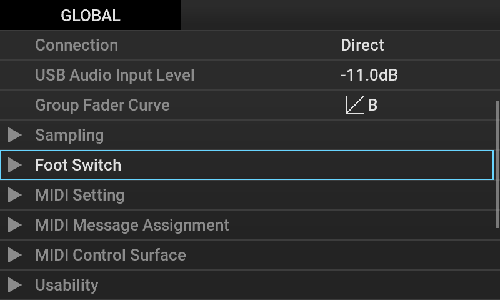
| Item | Setting value | Description | |
|---|---|---|---|
| Velocity Sense Set the sensitivity of the velocity of the Trigger Pad. [Default: 3] | OFF / 1 to 5 | Horizontal axis: Input strength Vertical axis: Output strength If the lower value is set, the strong sound is output even when you hit softly. When OFF is selected, a Trigger Pad is always played at Velocity = 100.
| |
| Trigger Threshold [Default: 1] | 1 to 127 | Set the lowest sensitivity of the Trigger Pad. | |
| Quantize Resolution Set the range of timing correction for the Quantize function. [Default: 1/1 Beat (Dly/Adj)] |
| When recording Recording will wait until the timing of the selected value is reached. When playing When you select the (Dly/Adj) option in the parameter settings, the timing to start playback from the Trigger Pad is adjusted to match the nearest specified resolution width. When you select a value written as (Dly) in the parameter, playback will wait until the timing at which you want to play the Trigger Pad is reached. However, if you play another Trigger Pad within one beat after starting the first Trigger Pad while all other Pads are stopped, playback will start immediately without waiting for the set value. | |
| Time Signature Set the time signature per bar. [Default:4/4] | 1/4 to 11/4 | The explanations in this manual assume that Time Signature is set to 4/4 unless otherwise specified. | |
| FX Release When you take your hand off the Touch Pad to turn the Effect off, set the effect that smoothly decays after the Delay Effect synchronized with BPM Out is applied. The effect can be applied in some cases but not others depending on the Kaoss Pad Effect. Kaoss Pad Effect List [Default: Enable] | Enable | Enables the FX Release function. | |
| Disable | Disables the FX Release function. | ||
| Connection Sets the method to connect to another device. When connecting this unit to the Send/Return jack of the DJ mixer, etc. to use it as an external effector, set to "Send". [Default: Direct] | Direct | Outputs both the input sound and the effect sound from this unit. If you are not touching the Touch Pad, the input sound is output as it is. | |
| Send | Only outputs the effect sound from this unit without outputting the input sound. | ||
| USB Audio Input Level Set the input level for USB Audio. [Default: +0.0 dB] | -36.0 dB to +12.0 dB | Set this value in 0.5 dB increments.
| |
| Group Fader Curve Set the level transition curve of the GROUP A/B fader. [Default: B] | B | Horizontal axis: Fader position Vertical axis: Volume If you select the setting value beginning with "Reverse", the level transition direction is reversed. | |
C | |||
D | |||
ReverseB | |||
ReverseC | |||
ReverseD | |||
| Sampling | Auto Play After Loop Sampling | Plays the Sample immediately from the point where Loop Sampling ends. | |
| Metronome Level [Off, 1, 2, 3, 4, 5] | Set the metronome volume in the sampling standby state and during sampling. The metronome sound is only output to Monitor Bus, which can be listened to with headphones. Sampling/Resampling Monitoring the audio | ||
| Sampling Pre Count [Off, 1 Bar, 2 Bar, 4 Bar] | Set the number of bars for the Pre Count before recording begins when you start Sampling or Resampling with all Trigger Pads stopped. Sampling/Resampling Monitoring the audio | ||
| Foot SW Mode Set Foot Switch function. [Default: Tap Tempo] | Tap Tempo | Use the Foot Switch to perform the same operation as the [TAP] button. | |
| Touch Hold | Use the Foot Switch to perform the same operation as the [TOUCH HOLD] button. | ||
| Sampling | Starts sampling using the Foot Switch. Sampling using the Foot Switch Perform Sampling for the same Trigger Pad as the previous Sampling. | ||
| Resampling | Starts Resampling using the Foot Switch. Perform Resampling for the same Trigger Pad as the previous Sampling. | ||
| Foot SW Polarity Set the polarity of the Foot Switch. [Default: [ - (KORG Standard)]] | [ - (KORG Standard)] / [+] | - | |
| MIDI Setting | MIDI Channel Set a channel of MIDI Message (Channel Message) including channel information. [Default: 1] | 1 to 16 | The channel number specified here is selected for both the MIDI input and MIDI output. |
| Clock Source Set the source of MIDI Clock. [Default: Internal] | Internal | BPM Out is used as the source of MIDI Clock to output MIDI Clock to the MIDI OUT jack and USB MIDI. | |
| External USB | BPM Out synchronizes with MIDI Clock input from the USB MIDI IN.
| ||
| External MIDI | BPM Out synchronizes with MIDI Clock input from the MIDI IN jack.
| ||
| MIDI Receive Routing Set the receiving route for MIDI Message other than MIDI Clock. [Default: MIDI] | MIDI | Send and receive MIDI Message using the MIDI IN jack and MIDI OUT jack. | |
| USB | Send and receive MIDI Message using the USB jack. This setting is also available when this unit is not connected to the PC. Even when the USB flash drive is disconnected, the mode is not automatically switched to the message received from the MIDI IN jack. | ||
| MIDI Message In/Out Feature Set whether to enable (Enable: place a check mark) or disable (Disable: no check mark) MIDI input/output Message. This works on both the MIDI IN and MIDI OUT. If Disable is selected, MIDI is not transferred. [Default: Enable for all] | Note | - | |
| Control Change | - | ||
| Program Change | - | ||
| Master Volume | - | ||
| MIDI Message Assignment Set "Control Change No." and "Note No." of MIDI Message. | The "Number" column of the MIDI Message Assignment table shows the default setting values, each of which can be changed by the user. MIDI Message Assignment Table | ||
| MIDI Control Surface Set the MIDI Message to be sent with MIDI Control Surface. | MIDI Control Surface Table | ||
| Usability | Caution Set the warning display. [Default: Enable] | Enable/Disable | - |
| Notice Set the notice display. [Default: Enable] | Enable/Disable | - | |
| Auto Power Off Set the automatic power-off. [Default: Enable] | Enable/Disable | About the automatic power-off | |
| LCD Brightness Set the screen brightness. [Default: 8] | 0 to 10 | - | |
| Load Global... Load the setting data of the GLOBAL function from the SD card. | - | The main unit settings are changed to the contents loaded from the SD card. | |
| Save Global As... Save the setting data of the GLOBAL function on the SD card. | - | Save the current main unit settings on the SD card. | |
| System | System Update... Perform the system update operation. | - | Update the system of this unit. For details, visit the KORG website. |
| Factory Reset... Reset this unit to the factory settings. | - | Reset the built-in memory to the factory settings. The contents (demo project) of the SD card cannot be restored. | |
| License... Displays the license of software products and other items. | - | - | |
| About... Displays the version number of this unit and the two-dimensional code to access the online manual. | - | - | |
Changing the background image
Place an image file in the specified format in the root directory of the SD card and insert the SD card into the main unit. Then it can be displayed as the background image of the KAOSS PAD performance screen.
- Format that can be displayed as a background image: BMP (uncompressed)
- Width: 800 pixels
- Height: 480 pixels or 430 pixels (For 480 pixels, the image is displayed in full screen. For 430 pixels, it is displayed bottom-aligned.)
- Bit depth: 24 bits
- File name: wall_paper.bmp
- Copy the image file of the specified format to the root directory of the SD card.
SD Card Reader - Insert the SD Card into the main unit.
The "Loading Wallpaper…" message is displayed on the screen for a few seconds, then the message disappears automatically and the background image of the KAOSS PAD performance screen is changed.
Hint
- Home
- Surface function
Surface function
Using the Surface function, you can connect this unit to the PC and use it as an SD card reader or as a controller for external MIDI devices.
- In Shift mode, press the [GLOBAL] button.
The "SURFACE" screen is displayed.- If you set each operation mode from the "SURFACE" screen, all the performances are stopped.
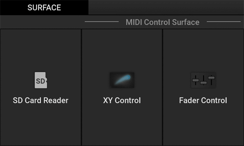
| SD Card Reader | Connect this unit and the PC using the USB cable to use this unit as the SD card reader. | |
| MIDI Control Surface | XY Control | Assigns any Control Change to each of the X-axis (horizontal axis) and Y-axis (vertical axis) on the Touch Pad of this unit, and uses it for MIDI performance. |
| Fader Control | Displays eight fader operators on the Touch Pad of this unit, assigns any Control Change to each operator, and uses them for MIDI performance. | |
- Home
- Surface function
- SD Card Reader
SD Card Reader
Connect this unit to the PC, and use it as an SD card reader.
While using the SD Card Reader Surface, you can operate the data on the SD card of this unit from the PC.
- Press "SD Card Reader" on the "SURFACE" screen.
The "SD Card Reader" screen is displayed.- On the screen, a message is displayed to notify that SD Card Reader Surface is running.
- Functions other than SD Card Reader are not available.
- If you hold down the [SHIFT] button after ejecting the USB flash drive in the PC side, SD Card Reader Surface exits, and the display returns to the original screen.
- USB Audio is disabled.
- The [LINE/PHONO IN] input and [MIC] input are turned off automatically.
- Home
- Surface function
- MIDI Control Surface
MIDI Control Surface
XY Control and Fader Control, which use this unit as a MIDI controller, can control the external MIDI devices such as a synthesizer and the software synthesizer on the computer.
While the MIDI Control Surface is running, the following operations are performed.
- Use each button, knob, fader, and Touch Pad to operate the MIDI Message output. (The MIDI Message corresponding to each operation cannot be directly assigned to the [SHIFT] button, [TAP] button, and [DATA ENTRY] knob.)
- If you hold down the [SHIFT] button, MIDI Control Surface exits, and the system returns to Kaoss Pad mode.
- If you use the [DATA ENTRY] knob or if you press the [TAP] button several times, you can set the BPM Out value. (When MIDI Clock Source is set to "Internal")
- USB Audio is disabled.
- The [LINE/PHONO IN] input and [MIC] input are turned off automatically.
- Home
- Surface function
- MIDI Control Surface
- XY Control
XY Control
Assign MIDI Message to the horizontal and vertical axes on the Touch Pad, and control the external MIDI devices with touch operations.
- Press "XY Control" on the "SURFACE" screen.
The "MIDI CONTROL SURFACE" screen (XY Control) is displayed.- You can set each parameter for the button, knob, fader, and Touch Pad with the "MIDI Control Surface" in the main unit settings.
Setting the main unit - For example, if you set "MinValue = 90" and "MaxValue = 20" to the [MONITOR MIX] knob, the value "90" is output when the knob is turned all the way to the left, and the value changes to 89, 88, 87, … 21 when the knob is turned to the right. When the knob is turned all the way to the right, the value "20" is output.
- You can set each parameter for the button, knob, fader, and Touch Pad with the "MIDI Control Surface" in the main unit settings.
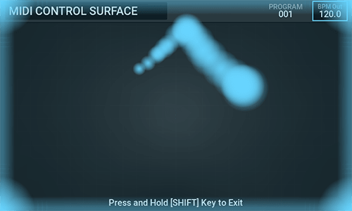
- Home
- Surface function
- MIDI Control Surface
- Fader Control
Fader Control
Assign any MIDI Message to each of eight faders on the screen, and use it like a mixer fader control.
- Press "Fader Control" on the "SURFACE" screen.
The "MIDI CONTROL SURFACE" screen (Fader Control) is displayed.- You can set each parameter for the button, knob, fader, and Touch Pad with the "MIDI Control Surface" in the main unit settings.
Setting the main unit
- You can set each parameter for the button, knob, fader, and Touch Pad with the "MIDI Control Surface" in the main unit settings.
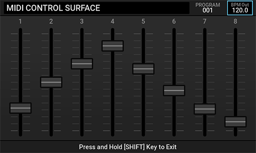
- Home
- Specifications
Specifications
| Kaoss Pad Effect | 209 types |
| Effect exclusive for microphone | TONE, DELAY, REVERB |
| Max. number of projects | 100 |
| Trigger pad | 16 (supports velocity) × eight banks |
| Hot cue | Max. 12 (per trigger pad) |
| Number of simultaneous plays | 16 |
| Audio specifications | Linear PCM (48 kHz/16 bits) |
| Recording functions | Sampling, resampling * Max. 30 min. |
| LIVE REC * Max. 100 min. | |
| Audio input | LINE/PHONO IN jack: RCA pin jack (Select LINE or PHONO.) |
| PHONO GAIN switch (LO/HI) | |
| MIC IN jack: Standard phone jack (φ 6.3 mm, monaural TS) * Exclusive for Dynamic Microphone | |
| AUX IN jack: Stereo mini jack (φ 3.5 mm) * Mix directly to LINE OUT. | |
| Audio output | LINE OUT jack: RCA pin jack |
| HEADPHONES jack: Standard stereo phone jack (φ 6.3 mm) | |
| Controller input | FOOT SW jack: Standard phone jack (φ 6.3 mm, TS) * Connect the optional PS-1 or PS-3. |
| USB jack | microB (MIDI, Audio (IN x 2ch, OUT x 34ch (48 kHz/16 bits, You need to install the KORG KaossReplay Audio Driver in the Windows environment.))) |
| MIDI jack | IN/OUT (DIN 5pin) and the MIDI function are exclusive to the USB jack (IN x 1 port, OUT x 1 port). |
| External storage | microSD card, microSDHC card (32GB Max) * Class10 or higher, UHS-I (U1) recommended (However, this does not guarantee operations with all cards.) |
| Product dimensions | 185 (W) x 284 (D) x 56 (H) mm |
| Product weight | 2.0 kg * Excluding microSD card and AC adapter. |
| Power supply | DC 5V/3A |
| Accessories | Owner's manual (Quick Start Guide) |
| AC adapter | |
| USB cable (Type A to microB, 1 m) | |
| microSDHC Card (inserted into the microSD card slot of the main body at time of shipment.) |
- The specifications are subject to change without notice for the purpose of improvement.
- Various names, company names, product names, etc. described in the text are trademarks or registered trademarks of their respective companies. Some ™ and ® marks are not used in the text.
- Home
- Troubleshooting
Troubleshooting
If this unit does not operate normally during use, check the following items.
If this does not solve the problem, or if there is an error that is not described here, unplug the AC adapter from the outlet and contact KORG Customer Service
| Symptom | Cause | Remedy |
|---|---|---|
| The MAIN OUT sound is not output from the [PHONES] jack. | The [MONITOR MIX] knob is turned all the way to the MONITOR side | Turn the [MONITOR MIX] knob in the MAIN side. |
| No sound is output from the [PHONES] jack. | The [PHONES VOLUME] knob is turned all the way to the left. | Turn the [PHONES VOLUME] knob clockwise little by little. |
| No sound is output from the [LINE OUT] jack. | The [OUTPUT VOLUME] knob is turned all the way to the left. | Turn the [OUTPUT VOLUME] knob clockwise little by little. |
| The sound input to the [MIC] jack is not output. | The [MIC] button is set to OFF (turns off). | Press the [MIC] button to set to ON (light up). |
| The sound input to the [LINE/PHONO IN] jack is not output. | The [LINE/PHONO] button is set to OFF (turns off). | Press the [LINE/PHONO] button to set to ON (light up). |
| The sound input to the [AUX IN] jack is not output from the [LINE OUT] jack. | The [OUTPUT VOLUME] knob is turned all the way to the left. | Turn the [OUTPUT VOLUME] knob clockwise little by little. |
| The sound input to the [AUX IN] jack is not output from the [PHONES] jack. | Specifications. The sound input to the [AUX IN] jack is not output from the [PHONES] jack. | The sound input to the [AUX IN] jack is output from the [LINE OUT] jack. |
| When you play a Trigger Pad, the volume does not change even if you hit the Trigger Pad with different strength impacts. | The Trigger Pad is set to SONG or LOOP. | The volume can be changed by the strength with which you hit the Trigger Pad only when it is set to 1-SHOT. |
| A different Trigger Pad from the one you hit reacts. | If a Trigger Pad is hit with a strong force, the sensor of another Trigger Pad that has not been hit may mistakenly recognize that it has been hit. | Do not hit the Trigger Pad harder than necessary. |
| The Kaoss Pad Effect does not work. | The [FX DEPTH] knob is turned all the way to the left. | Turn the [FX DEPTH] knob clockwise. |
| It is difficult to recognize the effect of a Kaoss Pad Effect in some cases. | If the input volume to Effect is too low, it may be difficult to recognize the effect. | Adjust the INPUT VOLUME, LEVEL of the Trigger Pad, and others so that the input volume to the Effect is appropriate. |
| Noises or abnormal sounds may be mixed in the output sound depending on the type of a Kaoss Pad Effect. | The input sound is too loud. | For the type that has the gain function within the Effect, a distortion may occur. It may be improved by lowering the volume of the input sound or adjusting the position at which you touch the Touch Pad. |
| The output sound may be silent depending on the type of a Kaoss Pad Effect. | This problem may occur when you change the Effect type while touching the Touch Pad. | For the Effect type that records the input sound when the Touch Pad is not touched and plays from the time it is touched, try not touching the Touch Pad for a period of time. |
| Even if you select the Kaoss Pad Effect type in the VOICE category, you will not get the expected effect. | You are entering chords or music. | The Effect type in the VOICE category assumes that you use the Solo vocal audio input with no Effect applied. If you enter chords or music, you will not get the expected effect. |
| The power turns off automatically after a certain period of time elapses. | The Auto Power OFF function is enabled. | Set the Auto Power OFF function to Disable. |
| Works when the Foot Switch is released, not stepped on. | The Foot Switch setting does not match. | Open the GLOBAL screen, and change the Foot SW Polarity setting. |
| Data corruption noise in the samples recorded through Sampling, Resampling, or Live Recording. | Samples are saved to an SD card. This problem may be caused by repeatedly saving and deleting data on the SD card. | This problem may be resolved by formatting the SD card. |


- Home
- Appendix
- MIDI Specifications
- MIDI Message Assignment Table
MIDI Message Assignment Table
※ outside of "MIDI Control Surface"
| Controller | Message Type | Number(Default) | Value Range | |
|---|---|---|---|---|
| Transmitted | Received | |||
| Touch Pad X | CC | 12 | 0-127 | 0-127 |
| Touch Pad Y | CC | 13 | 0-127 | 0-127 |
| Touch Pad Tap | CC | 92 | [Off] 0 [On] 127 | [Off] 0-63 [On] 64-127 |
| TOUCH HOLD | CC | 95 | [Off] 0 [On] 127 | [Off] 0-63 [On] 64-127 |
| FX DEPTH | CC | 94 | 0-127 | 0-127 |
| LEVEL A (GROUP A) | CC | 86 | 0-127 | 0-127 |
| LEVEL B (GROUP B) | CC | 87 | 0-127 | 0-127 |
| HOT CUE [1 - 12] | CC | 102-113 | [Off] 0 [On] 127 | [Off] 0-63 [On] 64-127 |
| PROGRAM MEMORY [1-12] | Program Change | - | 0-127 | x |
| Trigger Pad [1-16] (BANK [A-H]) | Note | 0-127 | [Off] 64 [On]1-127 | [Off] - [On] 1-127 |
- Home
- Appendix
- MIDI Specifications
- MIDI Control Surface Table
MIDI Control Surface Table
| Menu1 | Menu2 | Menu3 | Value Range (*Default) |
|---|---|---|---|
| Touch Pad Drag | XY Control X | Assign Type | No Assign/Control Change (*Control Change) |
| MIDI Channel | 1-16 (*1) | ||
| CC Number | 0-119(*12) ※default value is different for each switch | ||
| Min Value | 0-127(*0) | ||
| Max Value | 0-127(*127) | ||
| XY Control Y | same as "XY Control X" | ||
| Fader Control [1-8] | same as "XY Control X" | ||
| Touch Pad Tap | - | Assign Type | No Assign/Note/Control Change/Start/Continue/Stop ※ default value is different for each switch |
| MIDI Channel | 1-16 (*1) | ||
| CC Number | 0-119(*92) ※ default value is different for each switch | ||
| Off Value | 0-127(*0) | ||
| On Value | 0-127(*127) | ||
| Switch Type | Momentary(*)/Toggle | ||
| Key | LINE/PHONO | same as "Touch Pad Tap" | |
| MIC | same as "Touch Pad Tap" | ||
| TRIGGER PAD EDIT | same as "Touch Pad Tap" | ||
| CARD | same as "Touch Pad Tap" | ||
| GLOBAL | same as "Touch Pad Tap" | ||
| PROJECT | same as "Touch Pad Tap" | ||
| PROGRAM WRITE | same as "Touch Pad Tap" | ||
| MONITOR | same as "Touch Pad Tap" | ||
| AUTO BPM | same as "Touch Pad Tap" | ||
| A/E | same as "Touch Pad Tap" | ||
| B/F | same as "Touch Pad Tap" | ||
| C/G | same as "Touch Pad Tap" | ||
| D/H | same as "Touch Pad Tap" | ||
| HOT CUE | same as "Touch Pad Tap" | ||
| KAOSS PAD | same as "Touch Pad Tap" | ||
| TOUCH HOLD | same as "Touch Pad Tap" | ||
| PAD MOTION | same as "Touch Pad Tap" | ||
| SAMPLING | same as "Touch Pad Tap" | ||
| HOT CUE/PROGRAM MEMORY [1-12] | same as "Touch Pad Tap" | ||
| GATE | same as "Touch Pad Tap" | ||
| MUTE | same as "Touch Pad Tap" | ||
| SOLO | same as "Touch Pad Tap" | ||
| VARIABLE PITCH | same as "Touch Pad Tap" | ||
| STRETCH SYNC | same as "Touch Pad Tap" | ||
| QUANTIZE | same as "Touch Pad Tap" | ||
| GROUP A | same as "Touch Pad Tap" | ||
| GROUP B | same as "Touch Pad Tap" | ||
| Knob | FX DEPTH | same as "XY Control X" | |
| MONITOR MIX | same as "XY Control X" | ||
| Fader | LEVEL A | same as "XY Control X" | |
| LEVEL B | same as "XY Control X" | ||
| Trigger Pad | Pad [01-16] | same as "Touch Pad Tap" |
※ Assign Type
If Assign Type is switched, the Edit item changes as shown below.
| Assign Type | Edit item | Setting value |
|---|---|---|
| Note(※3,※4) | MIDI Channel | 1-16 |
| Note Number | C-1 - G9 | |
| Switch Type | Momentary/Toggle(※2) | |
| Control Change | MIDI Channel | 1-16 |
| Control Number | 0-119 | |
| Off Value /Min Value(※1) | 0-127 | |
| On Value /Max Value(※1) | 0-127 | |
| Switch Type | Momentary/Toggle(※2) | |
| Start | ||
| Continue | ||
| Stop |
(*1) If the target operators are Fader, Touch Pad Drag, etc. of which the value changes continuously, Min Value or Max Value changes. If the target operators are switches (Off/On binary representation), Off/On Value and the parameter item name change.
(*2) If Momentary is set, the following value is sent.
- Note On and On Velocity [Value] when a button is pressed
- Note Off and Off Velocity [Value] when a button is released
(*3) About the Note On Velocity value
- The trigger pads (1 to 16) are related to the "Global" - "Velocity Sense" setting in the main body settings. When Velocity Sense is set to 1 to 10, values 1 to 127 are sent depending on how strongly you hit the trigger pad. When Velocity Sense is set to 0, the value 100 is always sent.
- For other buttons, the value 100 is always sent regardless of the "Global" - "Velocity Sense" setting in the main body settings.
* If Toggle is set, the following values are alternately sent each time a button is pressed (based on the example where Assign Type is set to NOTE).
- Note On and On Velocity [Value]
- Note Off and Off Velocity [Value]
- The LED of the No Assign button does not light up even when it is pressed.
- The Note Off message uses (8 nh, V = 40 h).
If the operator is Knob or Fader, set the following items.
| Item | Setting value |
|---|---|
| MIDI Channel | 1-16 |
| Control Change Number | 0-119 |
| Min Value | 0-127 |
| Max Value | 0-127 |
- Home
- Appendix
- MIDI Specifications
- MIDI: Implementation Chart
MIDI: Implementation Chart
Model:KAOSS Replay Date:2024.04.01
Version:2.00
| Function | Transmitted | Received | Remarks | |
|---|---|---|---|---|
| Basic Channel | Default Change | 1-16 1-16 | 1-16 1-16 | Memorized |
| Mode | Memorized Messages Altered | x ******** | 3 x x | |
| Note Number: | True Voice | 0-127 ******** | 0-127 ******** | *N |
| Velocity | Note On Note Off | o9n,V=1-127 x8n,V=64 | o9n,V=1-127 x | *3 *5 |
| After touch | Key's Channel | x x | x x | |
| Pitch Bend | x | x | ||
| Control Change | 0, 32 | 〇 *B | 〇 | Bank Select *P *B |
| 0-127 | 〇 | 〇 | As control source *C | |
| Program Change | Variable Range | 〇 0-127 ******** | 〇 0-127 0-127 | *P |
| System Exclusive | 〇 | 〇 | *M *4 | |
| System Common | : Song Position : Song Select : Tune | x x x | x x x | |
| System Real Time | : Clock : Command | 〇 〇 | 〇 x | *1 *2 |
| Aux Message | : Local On/Off : All Note Off : Active Sense : Reset | x x 〇 x | x x x x | |
| Notes *N,*C,*P:Transmitted/received when the MIDI Message In/Out Feature(Note,Control Change, Program Change) is enabled. *M : Received when the MIDI Message In/Out Feature (Master Volume) is enabled. *B : This message is transmitted/received except in the "MIDI Control Surface" mode. *1 : When the Clock Source is Internal, it transmits but does not receive, and vice versa when the Clock Source is External MIDI or External USB. *2 : Transmitted in "MIDI Control Surface" mode. *3 : When the Play Mode is Loop or Song, the received velocity is always recognized as 100 ,and the transmitted velocity is always fixed at 100. *4 : Supports universal system exclusive messages device inquiry and master volume. However, master volume is only supported receiving. *5 : In "MIDI Control Surface" mode, Velocity can be set to any value (0-127). | ||||
Mode 1: OMNI ON, POLY Mode 2: OMNI ON, MONO o:Yes
Mode 3: OMNI OFF, POLY Mode 4: OMNI OFF, MONO x:No
Kaoss Pad Effect List
FX Release
- 〇: The Effect type that supports the FX Release function.
- Blank: The Effect type that does not support the FX Release function.
For details about the FX Release function, refer to FX Release in "Setting the main unit".
BPM Sync
- 〇: The Effect type that synchronizes with the BPM Out value.
- Blank: The Effect type that does not synchronize with the BPM Out value.
(However, the FX Release function synchronizes with BPM Sync.)
FX Category:VOICE
- The maximum effect is achieved by inputting a single voice (vocal) with no effects being applied.
- If you specify Key (C to B) and Scale (Major/Minor) for an Effect for which Assign is set to "Key&Scale", the pitch is corrected according to that Key and Scale.
| Program No. | Program Name | Category | X-Assign | Y-Assign | Fx Release | BPM Sync |
|---|---|---|---|---|---|---|
| FLT.01 | Low Pass Filter | FILTER | Cutoff | Resonance | 〇 | |
| FLT.02 | High Pass Filter | FILTER | Cutoff | Resonance | 〇 | |
| FLT.03 | Band+ Filter | FILTER | Cutoff | Resonance | 〇 | |
| FLT.04 | 72dB LPF | FILTER | Cutoff | Resonance | 〇 | |
| FLT.05 | Morphing Filter | FILTER | Cutoff | Resonance | 〇 | |
| FLT.06 | Vowel Filter | FILTER | 1st Formant | 2nd Formant | 〇 | |
| FLT.07 | Mid Cut Filter | FILTER | Cutoff | Resonance | 〇 | |
| FLT.08 | Isolator | FILTER | Low - Mid - Hi | Level | 〇 | |
| FLT.09 | Dist Isolator | FILTER | Low - Mid - Hi | Distortion | 〇 | |
| FLT.10 | Center Cancel | FILTER | Cutoff | Resonance | 〇 | |
| FLT.11 | Radio | FILTER | Tone | Level | 〇 | |
| FLT.12 | Telephone | FILTER | Tone | Stereo - Mono | 〇 | |
| FLT.13 | Reverb Filter | FILTER | Cutoff | Resonance | 〇 | |
| FLT.14 | LPF Delay | FILTER | Delay Time | Cutoff | 〇 | 〇 |
| FLT.15 | HPF Delay | FILTER | Delay Time | Cutoff | 〇 | 〇 |
| FLT.16 | BPF+ Delay | FILTER | Delay Time | BPF Cutoff & Resonance | 〇 | |
| FLT.17 | LPF&Reverb | FILTER | Reverb Depth | LPF Cutoff & Resonance | ||
| FLT.18 | HPF&Reverb | FILTER | Reverb Depth | HPF Cutoff & Resonance | ||
| FLT.19 | BPF+&Reverb | FILTER | Reverb Depth | BPF Cutoff & Resonance | ||
| FLT.20 | Radio Isolator | FILTER | Mid+Low - Mid - Mid+Hi | Level & Drive | 〇 | 〇 |
| FLT.21 | Isolator&Delay | FILTER | Low - Mid - Hi | Delay Depth | 〇 | |
| FLT.22 | Reverb Filter | FILTER | LPF - HPF | Resonance | ||
| FLT.23 | HPF/LPF Pan | FILTER | HPF-LPF, L-R Pan | Cutoff Frequency | 〇 | |
| FLT.24 | Dist LPF/HPF | FILTER | Cutoff Frequency | Distotion | ||
| MOD.25 | Vinyl Break | MODULATION | Stop Speed | Scratch | ||
| MOD.26 | Break Reverb | MODULATION | Stop Speed | Scratch | ||
| MOD.27 | Jet | MODULATION | Tone (Delay Time) | Feedback | 〇 | |
| MOD.28 | Jet- | MODULATION | Delay Time | Feedback | 〇 | |
| MOD.29 | Manual Phaser | MODULATION | Cutoff | Resonance | 〇 | |
| MOD.30 | Talk Filter | MODULATION | 1st Formant | 2nd Formant | 〇 | |
| MOD.31 | Digi Talk | MODULATION | 1st Formant | 2nd Formant | 〇 | |
| MOD.32 | Decimator | MODULATION | Sample Rate & Cutoff | Bit Depth | 〇 | |
| MOD.33 | Decima&HPF | MODULATION | Decimator Frequency & Bit | HPF Cutoff & Resonance | 〇 | |
| MOD.34 | Fuzz Distortion | MODULATION | Tone | Distortion | 〇 | |
| MOD.35 | Bass Distortion | MODULATION | Tone | Distortion | 〇 | |
| MOD.36 | Ring Mod HPF | MODULATION | Ring Mod Frequency | Cutoff | 〇 | |
| MOD.37 | Pitch Shift HPF | MODULATION | Pitch | Cutoff | 〇 | |
| MOD.38 | Mid Pitch Shift | MODULATION | Pitch | Pitch Shift Depth | 〇 | |
| MOD.39 | Broken Mod | MODULATION | Frequency | Depth | 〇 | 〇 |
| MOD.40 | Pitch&Dly | MODULATION | Pitch Shift | Delay Depth | 〇 | |
| MOD.41 | Harmonic Pitch | MODULATION | Root-min3rd-Maj3rd-4th-5th | Reverb Level (Y Up Side) | ||
| MOD.42 | Delay/Tremolo Rv | MODULATION | Delay Time, Speed | Tremolo-Delay Balance | 〇 | |
| MOD.43 | Decimator Slicer | MODULATION | Fs / Speed | Bit / Slice Level | 〇 | 〇 |
| MOD.44 | Dual Modulator | MODULATION | Mod Freq | Mod Level | 〇 | |
| MOD.45 | Manual Flutter | MODULATION | Flutter | Cutoff Frequency | ||
| DYN.46 | Compressor | DYNAMICS | Sensitivity | Attack | 〇 | 〇 |
| DYN.47 | Ducking Comp | DYNAMICS | Ratio | Threshold | 〇 | |
| DYN.48 | LowBoost Comp | DYNAMICS | Comp Sensitivity | Level Adjust | 〇 | |
| DYN.49 | Lofi Comp HPF | DYNAMICS | Sensitivity | Cutoff Frequency (UpSide) | ||
| DYN.50 | Hard Limiter | DYNAMICS | Attack Time | Threshold | 〇 | |
| DYN.51 | Touch Ducking | DYNAMICS | Release | Depth | ||
| DYN.52 | EnvTrigSubBass | DYNAMICS | Boom Decay | Boom Pitch | ||
| LFO.53 | LFO LPF | LFO | LFO Speed | Resonance | 〇 | 〇 |
| LFO.54 | LFO HPF | LFO | LFO Speed | Resonance | 〇 | 〇 |
| LFO.55 | LFO BPF+ | LFO | LFO Speed | Resonance | 〇 | 〇 |
| LFO.56 | LFO HPF+&Delay | LFO | Delay Time | HPF Level, Delay Depth | 〇 | |
| LFO.57 | Random LPF | LFO | LFO Speed | LFO Depth | 〇 | 〇 |
| LFO.58 | Random HPF+ | LFO | LFO Speed | LFO Depth | 〇 | 〇 |
| LFO.59 | Infinite Filter | LFO | LFO Speed | LFO Depth | 〇 | 〇 |
| LFO.60 | Jag Filter | LFO | LFO Speed | LFO Shape | 〇 | 〇 |
| LFO.61 | Step Filter | LFO | Curoff Frequency | Speed | 〇 | 〇 |
| LFO.62 | Broken Step Flt | LFO | Curoff Frequency | Speed | 〇 | 〇 |
| LFO.63 | Yoi Yoi | LFO | LFO Speed | Yoi Level | 〇 | 〇 |
| LFO.64 | Flanger | LFO | LFO Speed | Feedback | 〇 | 〇 |
| LFO.65 | Flanger Filter | LFO | LFO Speed | Cutoff | 〇 | 〇 |
| LFO.66 | Infinite Flanger | LFO | LFO Speed | Resonance | 〇 | 〇 |
| LFO.67 | Deep Flanger | LFO | LFO Speed | Feedback | 〇 | 〇 |
| LFO.68 | Mid Flanger | LFO | LFO Speed | Feedback | 〇 | 〇 |
| LFO.69 | Phaser | LFO | LFO Speed | Resonance | 〇 | 〇 |
| LFO.70 | Mid Phaser | LFO | LFO Speed | Resonance | 〇 | 〇 |
| LFO.71 | Step Phaser | LFO | Cutoff | Resonance | 〇 | 〇 |
| LFO.72 | Auto Pan | LFO | LFO Speed | Auto Pan Depth | 〇 | 〇 |
| LFO.73 | Mid Auto Pan | LFO | LFO Speed | Auto Pan Depth | 〇 | 〇 |
| LFO.74 | LFO Emphasizer | LFO | Emphasis | LFO Depth | 〇 | 〇 |
| LFO.75 | Slicer | LFO | LFO Speed | Slicer Depth | 〇 | 〇 |
| LFO.76 | Mid Slicer | LFO | LFO Speed | Slicer Depth | 〇 | 〇 |
| LFO.77 | LPF Slicer | LFO | LFO Speed | Cutoff | 〇 | 〇 |
| LFO.78 | HPF Slicer | LFO | LFO Speed | Cutoff | 〇 | 〇 |
| GRN.79 | Grain Shifter | LFO | Cycle Speed | Length | 〇 | |
| GRN.80 | Mix Grain | GRAIN | Cycle Speed | Length | 〇 | 〇 |
| GRN.81 | Mix Grain+ | GRAIN | Cycle Speed | Length | 〇 | 〇 |
| GRN.82 | Beat Grain | GRAIN | Cycle Speed | Mix Balance | 〇 | 〇 |
| GRN.83 | Grain&HPF | GRAIN | Grain Cycle Speed & Length | HPF Cutoff & Resonance | 〇 | 〇 |
| GRN.84 | Stutt Grain | GRAIN | Grain Speed | Decimator Depth | 〇 | 〇 |
| GRN.85 | 3 Grains | GRAIN | Loop Position | Pitch | ||
| DLY.86 | Delay | DELAY | Delay Time | Delay Depth | 〇 | |
| DLY.87 | Smooth Delay | DELAY | Delay Time | Delay Depth | ||
| DLY.88 | Ping Pong Delay | DELAY | Delay Time | Delay Depth | 〇 | |
| DLY.89 | Multi Tap Delay | DELAY | Delay Time | Delay Depth | ||
| DLY.90 | One Delay | DELAY | Delay Time | Delay Tone | 〇 | |
| DLY.91 | Tape Echo | DELAY | Delay Time | Delay Depth | 〇 | |
| DLY.92 | Dub Echo | DELAY | Delay Time | Delay Depth | 〇 | |
| DLY.93 | Feedback Echo | DELAY | Delay Time | Delay Depth | 〇 | |
| DLY.94 | Phaser Delay | DELAY | Delay Time | Resonance & Delay Depth | 〇 | |
| DLY.95 | Flanger Delay | DELAY | Delay Time | Resonance & Delay Depth | 〇 | |
| DLY.96 | Echo Break | DELAY | Delay Time | Feedback | 〇 | 〇 |
| DLY.97 | LoFi Echo Break | DELAY | Delay Time | Decimator Depth | 〇 | 〇 |
| DLY.98 | Low Cut Delay | DELAY | Delay Time | Delay Depth | 〇 | |
| DLY.99 | 3 Band Delay | DELAY | Low - Mid - Hi | Delay Depth | 〇 | |
| DLY.100 | Delay+Reverb | DELAY | Delay Time | Delay Depth, Reverb Depth | 〇 | |
| DLY.101 | Grain Delay | DELAY | Grain Length | Delay Depth | 〇 | |
| DLY.102 | BPF Time Slide | DELAY | Delay Time | Filter Cutoff | 〇 | |
| RVB.103 | Hall Reverb | REVERB | Reverb Time | Reverb Depth | ||
| RVB.104 | Room Reverb | REVERB | Reverb Time | Reverb Depth | ||
| RVB.105 | Spring Reverb | REVERB | Reverb Time | Reverb Depth | ||
| RVB.106 | Pump Reverb | REVERB | Reverb Tone | Pump Depth | 〇 | |
| RVB.107 | Freeze Reverb | REVERB | Reverb Tone | Mix Balance | 〇 | |
| RVB.108 | Reverb Break | REVERB | Reverb Tone | Slice Depth | 〇 | 〇 |
| RVB.109 | Pitch Verb | REVERB | Reverb Time | Pitch Shifter Level | ||
| RVB.110 | 3D PAN | REVERB | L-R Pan | Reverb Level | ||
| RVB.111 | Gate Reverb | REVERB | Reverb Tone | Threshold | ||
| RVB.112 | Harmonic Reverb | REVERB | Pitch | Reverb Level | ||
| RVB.113 | Cave Reverb | REVERB | Cutoff Frequency | Reverb Time | ||
| RVB.114 | Gate 7th Reverb | REVERB | Fine Pitch | Threshold | ||
| LOP.115 | F/R Looper | LOOPER | Looper Beat | Reverse - Forward | 〇 | 〇 |
| LOP.116 | Slice Looper | LOOPER | Looper Beat | Slice Position | 〇 | 〇 |
| LOP.117 | LPF Looper | LOOPER | Looper Beat | Cutoff | 〇 | 〇 |
| LOP.118 | HPF Looper | LOOPER | Looper Beat | Cutoff | 〇 | 〇 |
| LOP.119 | Iso Looper | LOOPER | Looper Beat | Low - Mid - Hi | 〇 | 〇 |
| LOP.120 | Flanger Looper | LOOPER | Looper Beat | Flanger Tone(Delay Time) | 〇 | 〇 |
| LOP.121 | Phaser Looper | LOOPER | Looper Beat | Cutoff | 〇 | 〇 |
| LOP.122 | Pitch Looper | LOOPER | Looper Beat | Pitch | 〇 | 〇 |
| LOP.123 | Deci Looper | LOOPER | Looper Beat | Decimator Depth | 〇 | 〇 |
| LOP.124 | Break Looper | LOOPER | Looper Beat | Stop Speed | 〇 | 〇 |
| LOP.125 | RwDelay Looper | LOOPER | Looper Beat | Cutoff | 〇 | 〇 |
| LOP.126 | Freeze Looper | LOOPER | Looper Beat | Cutoff | 〇 | 〇 |
| LOP.127 | High Looper | LOOPER | Looper Beat | Mix Balance | 〇 | 〇 |
| LOP.128 | Backing Looper | LOOPER | Looper Beat | Reverse - Forward | 〇 | 〇 |
| LOP.129 | OverDub Looper | LOOPER | Looper Beat | Loop - Overdub | 〇 | 〇 |
| LOP.130 | Shuttle Looper | LOOPER | Looper Beat | Cutoff | 〇 | 〇 |
| LOP.131 | Weird Looper | LOOPER | Looper Beat | Pitch Shift | 〇 | |
| LOP.132 | KP2 Looper | LOOPER | Looper Beat | Cutoff | 〇 | 〇 |
| LOP.133 | KP3 Looper | LOOPER | Looper Beat | Reverse - Forward | 〇 | 〇 |
| LOP.134 | KP3 RwLooper | LOOPER | Looper Beat | Pitch | 〇 | 〇 |
| LOP.135 | Loop Breaker | LOOPER | Looper Beat | Scratch | ||
| LOP.136 | Looper+Isolator | LOOPER | Looper Beat | HPF Cutoff & Resonance | 〇 | 〇 |
| LOP.137 | Looper+OSC | LOOPER | Looper Beat | Oscillator Pitch, etc. | 〇 | |
| LOP.138 | Looper+Noise | LOOPER | Looper Beat | Noise Level, etc. | 〇 | |
| LOP.139 | Reverse Looper+ | LOOPER | Looper Beat | Filter Cutoff | 〇 | 〇 |
| LOP.140 | Rewind Looper | LOOPER | Looper Beat | Rewind Spin - Forward | 〇 | 〇 |
| LOP.141 | Dual FLT/Looper | LOOPER | Looper Beat | Cutoff Frequency | 〇 | |
| VOC.142 | Unison Vocoder | VOCODER | Pitch | Tone | 〇 | |
| VOC.143 | Pulse Vocoder | VOCODER | Pitch | Vibrato Depth | 〇 | |
| VOC.144 | Chord Vocoder | VOCODER | Pitch | Chord (minor - major) | 〇 | |
| VOC.145 | Lofi Vocoder | VOCODER | Pitch | Decimator Depth | 〇 | |
| VOC.146 | Noise Vocoder | VOCODER | Tone | Level | 〇 | |
| VOC.147 | Vocoder Bass | VOCODER | Pitch | Vocoder Tone | 〇 | 〇 |
| VOC.148 | Vocoder M7 | VOCODER | Pitch | Vocoder Tone | 〇 | 〇 |
| VOC.149 | Vocoder m7 | VOCODER | Pitch | Vocoder Tone | 〇 | 〇 |
| VOX.150 | Pitch Corrector | VOICE | Key & Scale | Formant | ||
| VOX.151 | Cheap Corrector | VOICE | Key & Scale | VoPitch | ||
| VOX.152 | Pls Vocoder | VOICE | Key & Scale | Formant | ||
| VOX.153 | Pls2 Vocoder | VOICE | Key & Scale | Formant | ||
| VOX.154 | Saw Vocoder | VOICE | Key & Scale | Formant | ||
| VOX.155 | Tri Vocoder | VOICE | Key & Scale | Formant | ||
| VOX.156 | Squ Vocoder | VOICE | Key & Scale | Formant | ||
| VOX.157 | SynVcdr Pls | VOICE | Key & Scale | Cutoff & Resonance | ||
| VOX.158 | SynVcdr Pls2 | VOICE | Key & Scale | Cutoff & Resonance | ||
| VOX.159 | SynVcdr Saw | VOICE | Key & Scale | Cutoff & Resonance | ||
| VOX.160 | SynVcdr Tri | VOICE | Key & Scale | Cutoff & Resonance | ||
| VOX.161 | SynVcdr Sqr | VOICE | Key & Scale | Cutoff & Resonance | ||
| VOX.162 | Noise Vocoder | VOICE | Position | Focus | ||
| VOX.163 | Voice Changer | VOICE | Note | Formant | ||
| VOX.164 | Voice Changer PC | VOICE | Note | Formant | ||
| VOX.165 | Vcdr Chg Pls PC | VOICE | Note | Formant | ||
| VOX.166 | Vcdr Chg Pls2 PC | VOICE | Note | Formant | ||
| VOX.167 | Vcdr Chg Saw PC | VOICE | Note | Formant | ||
| VOX.168 | Vcdr Chg Tri PC | VOICE | Note | Formant | ||
| VOX.169 | Vcdr Chg Squ PC | VOICE | Note | Formant | ||
| VOX.170 | Vo Synth Pls | VOICE | Note | Cutoff & Resonance | ||
| VOX.171 | Vo Synth Pls2 | VOICE | Note | Cutoff & Resonance | ||
| VOX.172 | Vo Synth Saw | VOICE | Note | Cutoff & Resonance | ||
| VOX.173 | Vo Synth Tri | VOICE | Note | Cutoff & Resonance | ||
| VOX.174 | Vo Synth Sqr | VOICE | Note | Cutoff & Resonance | ||
| VOX.175 | Vo Synth Pls PC | VOICE | Note | Cutoff & Resonance | ||
| VOX.176 | Vo Synth Pls2 PC | VOICE | Note | Cutoff & Resonance | ||
| VOX.177 | Vo Synth Tri PC | VOICE | Note | Cutoff & Resonance | ||
| VOX.178 | Vo Synth Sqr PC | VOICE | Note | Cutoff & Resonance | ||
| VOX.179 | Vo LFO Tri | VOICE | LFO Speed | Formant | ||
| VOX.180 | Vo LFO Sin | VOICE | LFO Speed | Formant | ||
| VOX.181 | Vo LFO Tri PC | VOICE | LFO Speed | Formant | ||
| VOX.182 | Vo LFO Sin PC | VOICE | LFO Speed | Formant | ||
| SYN.183 | Rez Noise | SYNTH/SE | Tone | Resonance | 〇 | |
| SYN.184 | Pump Noise | SYNTH/SE | Tone | Pump Depth | 〇 | 〇 |
| SYN.185 | Bubble SE | SYNTH/SE | LFO Speed | LFO Depth | ||
| SYN.186 | Electric Perc | SYNTH/SE | Pitch | Release Time | ||
| SYN.187 | Disco Siren | SYNTH/SE | LFO Speed | Cutoff | ||
| SYN.188 | Kaoss Drone | SYNTH/SE | Cutoff | Feedback | ||
| SYN.189 | Uni Saw Synth | SYNTH/SE | Pitch | Cutoff | 〇 | |
| SYN.190 | Uni Squ Synth | SYNTH/SE | Synth Pitch | HPF Cutoff & Resonance | 〇 | |
| SYN.191 | Uni Saw Bass | SYNTH/SE | Synth Pitch | HPF Cutoff & Resonance | 〇 | |
| SYN.192 | Uni Squ Bass | SYNTH/SE | Pitch | Cutoff | 〇 | |
| SYN.193 | Metallic Synth | SYNTH/SE | Cutoff | LFO Speed | 〇 | |
| SYN.194 | SayYay Synth | SYNTH/SE | Pitch | Formant & Vibrato | 〇 | |
| SYN.195 | Lofi Talk | SYNTH/SE | Synth Pitch | 1st and 2nd Formant | 〇 | |
| SYN.196 | Siren | SYNTH/SE | LFO Speed etc... | LFO Intensity | 〇 | |
| SYN.197 | LFO Sin | SYNTH/SE | Synth Pitch, LFO Speed | HPF Cutoff & Resonance | 〇 | |
| SYN.198 | LFO Squ | SYNTH/SE | Synth Pitch, LFO Speed | HPF Cutoff & Resonance | 〇 | |
| SYN.199 | LFO 8-BIT PLS25 | SYNTH/SE | Synth Pitch | LFO Intensity | 〇 | |
| SYN.200 | LFO 8-BIT PLS12 | SYNTH/SE | Synth Pitch | LFO Intensity | 〇 | |
| SYN.201 | LFO 8-BIT TRI | SYNTH/SE | Synth Pitch | LFO Intensity | 〇 | |
| SYN.202 | 8-BIT FAMILY | SYNTH/SE | Synth Pitch | SE1 - SE2 | ||
| SYN.203 | Synth Looper | SYNTH/SE | Synth Tone | Looper Off - Looper On (Beat) | 〇 | 〇 |
| SYN.204 | DTMF | SYNTH/SE | Tone1 | Tone2 | ||
| SYN.205 | Modem | SYNTH/SE | Pattern | SE1 - SE2 | 〇 | |
| SYN.206 | Laser Sword | SYNTH/SE | Pitch | Modulation | ||
| SYN.207 | Photon Beam | SYNTH/SE | Pitch | Modulation | ||
| SYN.208 | Chick | SYNTH/SE | Pitch | Pitch Mod Int | ||
| SYN.209 | Spacy | SYNTH/SE | Pitch | Reverb Level |
Error Messages
If there is an error or confirmation item during the operation, a message is displayed on the screen.
| ID | Display contents | Description and remedy |
|---|---|---|
| Error display | ||
| E1 | SD CARD FULL | The system automatically stopped because the SD card ran out of space during live recording or Sampling. Delete unnecessary files to increase the amount of available storage space on the SD card. Deleting a file Deleting a project |
| E2 | INVALID PROJECT DATA | An inconsistency was detected in project data when a project is loaded. Reload the project, or load a normal project. |
| E3 | SD CARD READ ERROR | Cannot read from the SD card. Replace with a normal SD card. |
| E4 | SD CARD WRITE ERROR | Cannot write to the SD card. Replace with a normal SD card. |
| E5 | SD CARD MOUNT ERROR | Failed to mount the SD card. Insert the SD card again, or replace it with a normal SD card. |
| E6 | WAV FILE LENGTH ERROR | An attempt was made to import a WAV file that has the length of 30 or more minutes. Specify a WAV file that is shorter than 30 minutes in length. |
| Warning display | ||
| W1 | Current project has been changed, but not saved. | "New Project", "Load Project", or power-off was selected while the contents of the project are not saved. Save the project as needed. If it is not saved, the current project contents will be discarded |
| W2 | Same project name already exists. Overwrite? | An attempt was made to save the project with the same project name as the existing one. Change the project name as needed. If the project is saved with the same project name, the project file is overwritten. |
| W3 | Trigger Pad destination has an audio clip. Overwrite? | An attempt was made to execute the "Move", "Import", or "Copy" operation with the Trigger Pad Utility while audio clips exist in the "Destination". If such an operation is executed, the existing audio clips are overwritten with the new ones. |
| W4 | Rename destination already exist. Overwrite? | An attempt was made to rename the project with the same project name as the existing one. Change the project name as needed. If the project is renamed with the same project name, the project file is overwritten. |
| W5 | The current project must be saved before renaming. | "Rename" was selected while the contents of the project are not saved. Save the project as needed. |
| Notice display | ||
| C1 | Stop sample playback? | The menu for stopping playback was selected while playback is being performed by Sampler. If not stopping, press "Cancel". If you continue the selection without canceling, the playback operation stops. |
| C2 | Eject SD card? | The Eject SD Card menu was selected. If you do not want to eject the SD card, press "Cancel". |
| Notification display | ||
| N1 | No SD card | You have selected a menu that requires an SD card while no SD card is inserted or while the inserted SD card cannot be recognized due to damage, etc. Insert an SD card that can be used normally before operating. |
| N2 | SD card full | An attempt was made to write to an SD card that has no more available storage space. Insert an SD card with available storage space before operating. |
| N3 | The monitor resource has run out. | Could not perform Monitoring due to simultaneous playback conditions. Confirm the conditions for enabling the simultaneous playback. Listening with headphones |
| N4 | Select a sampling target pad. | A Sampling Target Pad has been selected with the Sampling/Resampling function. Select a sampling target pad. Sampling |
| N5 | Select an edit target pad. | An Edit Target Pad has been selected with the Trigger Pad Edit function. Select an Edit Target Pad. Setting an audio clip |
| N6 | Select a hot cue target pad. | Hot Cue Target Pad has been selected with the Hot Cue function. Select Hot Cue Target Pad. Setting the Hot Cue target |
| N7 | Sampling time has reached to max 30 min. | Sampling has reached the maximum time. The maximum sampling time is 30 minutes. |
| N8 | New project has been created. | A new project has been created with "New Project". |
| N9 | "LIVE REC" cannot be started. | Cannot start LIVE REC if there are 100 files from LiveRec00 to LiveRec99 when the SD card is inserted, or if there is not enough available storage space on the SD card. Organize the data on the SD card and check whether there is enough available storage space on the SD card. |
| N10 | No Edit Candidate. | There is no target pad (a Trigger Pad with audio clips assigned) that can be selected. Assign audio clips to one or more Trigger Pads. |
| N11 | No Hot Cue Candidate. | There is no Hot Cue Target Pad (a Trigger Pad with audio clips assigned) that can be selected. Assign audio clips to one or more Trigger Pads. |
| N12 | BPM could not be detected. | When Auto BPM is enabled and imported with "Import Audio Clip" of the Trigger Pad Utility, the BPM could not be automatically detected for some reason. Manually set BPM. Importing audio clips or WAV files |
| N13 | Illegal SD CARD format | The SD card has not been formatted. Please format the SD card. |