

SoundCloud

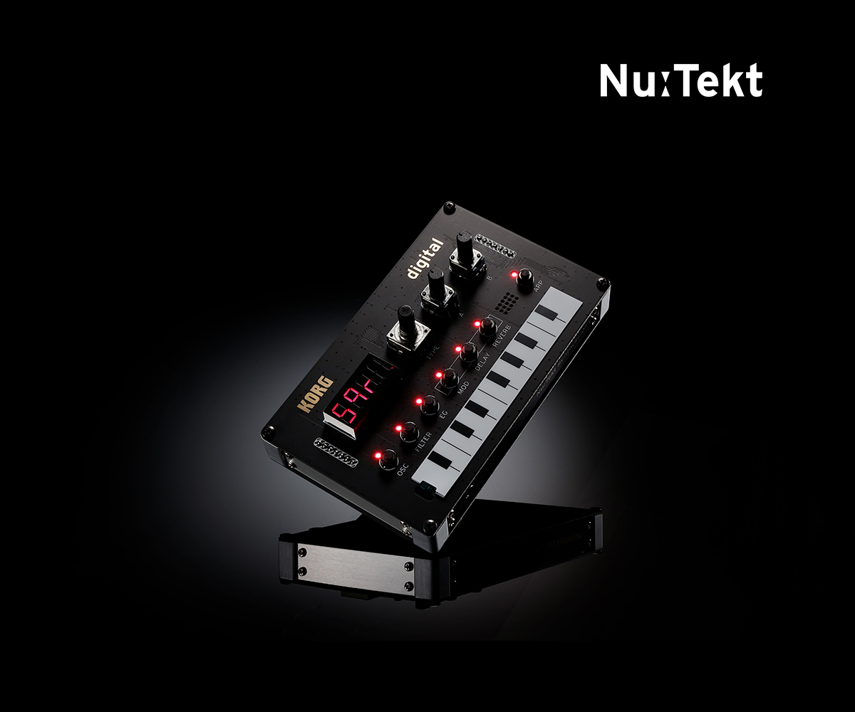
NTS-1 digital kit
PROGRAMMABLE SYNTHESIZER KIT
Learn More
Related Sites
Related Products


News
[DOTEC-AUDIO x Nu:Tekt] How to make Custom Effects for NTS-1
Creating custom plugins for the NTS-1 might seem pretty daunting, but fret not!
In this 5-part series of articles we will explore together with DOTEC-AUDIO how to create custom effects for NTS-1, step by step!

Article #1: Making Custom-Made Effects Work with the NTS-1
Hello, everyone! My name is Shinji Iijima from DOTEC-AUDIO, a plugin development company.
Up until now we have mostly developed audio plugins only for PC and iPhone / iPad.
https://dotec-audio.com/
The Nu:Tekt NTS-1 digital kit” (hereafter abbreviated as the “NTS-1) is an extremely interesting yet affordable build-it-yourself digital synthesizer kit. So, why is DOTEC-AUDIO, a PC plugin developer interested in this synthesizer? It's because this synth lets you write your own programs and then install the sounds (oscillators) and effects you've developed into the NTS-1.
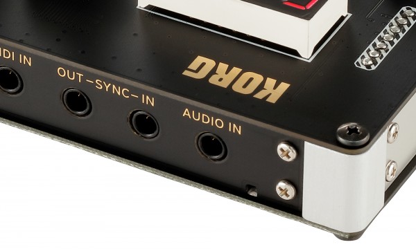
Another interesting thing about the NTS-1 is that it has a stereo audio input (line input). What this means is that you can hook up a sound generator or a musical instrument, and use this unit not just as a synthesizer but as a compact standalone effects unit.
In other words, you get a synthesizer that you can freely program, as well as effects. When you hear that, it really makes you want to try it yourself, don’t you think?
OK, so let’s get started. Take a look at this video!
And...
Both of these effects contain part of the multi-effects functionality from DOTEC-AUDIO’s “DeeFX,” brought to the NTS-1.
In this series, we’ll be publishing and delving into the source code of these effects; but to start out, I’ll explain how to download these two effects and install them into the NTS-1.
If you’ve already purchased an NTS-1, definitely download these effects and play with them yourself!
How to install
- 1/ Install the NTS-1 Sound Librarian
First of all, install the NTS-1 Sound Librarian software on your computer (Win/Mac).
Follow the instructions to install the software, and make sure to connect the NTS-1 to your computer. - 2/ Download the effect files
Next, download these effect files developed by DOTEC-AUDIO.
Download Bitcrusher here
Download Stop FX here
Decompressing this ZIP file will give you the “bitcrusher.ntkdigunit” and “stopfx.ntkdigunit” files. - 3/ Load these files into Sound Librarian
To load the files, go to the “File” menu, click “Import User Unit” and select the files you decompressed. Once you do this, the “bitcrusher” effect is added to the “USER MODULATION FX” category, and the “stopfx” effect is added to the “USER DELAY FX” category.
Last, go the “Send/Recv.” menu and select “Send User Data” to transfer these two effects to the NTS-1.
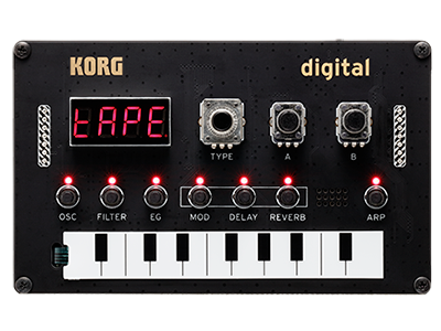
Once the effects are transferred, you’ll be able to select "bitcrusher" from “Mod”, and “stopfx” from "delay" on the NTS-1.
See you next time!
Article #2: How to Prepare to Develop Effects for the NTS-1
Hello, everyone! I’m Shinji Iijima from DOTEC-AUDIO.
Last time we talked about the effects we actually made for the NTS-1. Have you tried them out yet? This time, I’ll explain the environment you’ll need to create your own original effects (and oscillators) for the NTS-1.
Actually, the basics you need to know are found in the “logue SDK” page, so this time, I’ll be giving you some added details. I should mention that everything I’m explaining is available free of charge. Also, one of the appealing things about this is that you can develop in Windows, macOS or Linux, so just about anyone can do this.
(Note that the installation steps differ with each OS.)
logue SDK
https://korginc.github.io/logue-sdk/
To begin, let’s talk about what an “SDK” is. SDK stands for “Software Development Kit,” which is a set of tools necessary to develop specific software.
For instance, you’ll use the Windows SDK to develop apps for Windows, or the iOS SDK to develop apps for the iPhone. When developing for the NTS-1, we use the “logue SDK.”
https://github.com/korginc/logue-sdk
The SDK that’s released here is the logue SDK itself. The best thing to do is to use Git software to obtain the latest version of the SDK, but to do that you’ll need to know how to use Git.
For that reason, it’s fine just to go to the Web page listed above and click on the green “Clone or Download” button to download the files as a ZIP archive. Note that the SDK is sometimes updated, so it’s a better idea to use Git if you always want to obtain the latest version of the SDK.
MSYS2 (for Windows)
https://www.msys2.org/
The thorniest matter to deal with when you consider building an NTS-1 development environment for Windows is “MSYS2.” I’d like to explain about that now. All of the GNU commands used with the logue SDK execute commands with the Unix OS as a prerequisite.
For Linux, which is basically Unix, or macOS, which is based on Unix, you’ll be able to install using a bare minimum of tools. However, for Windows you’ll need an additional environment that can execute Unix commands. Simply put, MSYS2 is a platform for executing Unix commands on Windows. Because of this, if you’re developing with Windows and MSYS2, you’ll run your commands within the “MSYS2” window.
Run a Web search on “NTS-1 MSYS2,” and you’ll find articles that list the specific steps required. I definitely encourage you to use those sites for reference.
GNU Arm Embedded Toolchain
https://github.com/korginc/logue-sdk/tree/master/tools/gcc
To develop programs, you need a “compiler,” which is a software that converts programs written by humans into machine language that’s readable by a computer. With the logue SDK, we’ll use the “GNU Compiler Collection” (GCC for short).
The GCC is such a complicated topic in its own right that we could write a thick book about it, so I’ll skip that for now. Suffice to say that the “GNU Arm Embedded Toolchain” explained on this page is the name of a set of programming tools that includes the GCC.
The “Arm Embedded” refers to the “STM32F4” chip with an Arm CPU that’s used on the NTS-1. The toolchain we’re referring to is used to develop programs that run on this CPU.
As you can see in the Readme file, all you need to do to install is to run the prepared shell script.
GNU Make
https://github.com/korginc/logue-sdk/tree/master/tools/make
“Make” is a tool that lets you configure a single command to save you the trouble of executing many commands and compiling your files each time. (Make is another tool we could take up a whole book to write about.)
Make does not need any additional special installation on macOS, Linux and Windows (and MSYS2), but we will explain where it is otherwise necessary to install.
Info-ZIP
https://github.com/korginc/logue-sdk/tree/master/tools/zip
This is a tool used to create ZIP files, and as with GNU Make it doesn’t require special installation on virtually any platform.
logue-cli (optional)
https://github.com/korginc/logue-sdk/tree/master/tools/logue-cli
This is an “optional” component, and not everyone needs it. Think of this as the command-line variant of “Sound Librarian,” which we described last time. Note that there is a Windows and macOS version of Sound Librarian, but not a Linux version.
For that reason, if you’re planning to develop on Linux, you’ll need to install this tool. Once you’ve successfully installed these tools, let’s build (create the program for) the sample components included with the SDK.
We’ll use the steps in the “Demo Project Build (Waves)” (
https://korginc.github.io/logue-sdk/) to build.
If you’ve successfully executed the commands, a file named “waves.ntkdigunit” will be generated. This should be loaded into the “USER OSCILLATORS” of Sound Librarian as “waves.” If you’ve gotten this far, the next step is programming! It’s a bit of a chore to get things up and running.
The good thing is that there’s a lot of information on the Internet about these tools, so I encourage you to poke around on the Web to get your environment all set up!
See you next time!
Article #3: Creating an Original Effect, Part 1
Hello, my name is Frank Shigetora, and I’m a sound producer at DOTEC-AUDIO.
Since it’s time for us to create our effect, I’ll be in charge of this part, as the designer of the DSP.
Have you set up your development environment yet, as we explained last time?
I’ll be following up with those of you who have used the command line or who are creating a program environment for the first time.
With MSYS2, we’ll move to a different folder using the command “cd
For really long folder names, type a few of the initial characters, and then hit the TAB key to auto-complete with names that match, starting from the first character.
If you want to see a list of contents of the current folder, type the “ls” command and hit Enter.
So, you should just remember “cd” to move to a different folder, and “ls” to list its contents.
To move back up one level in the directory, type “cd ..” (two periods).
Actually, on UNIX-based systems, we use the term “directory” for a folder; but since we’re using Windows and the Mac as well, we’ll stick with the term “folder” for now. (This probably won’t ruffle any feathers, but just in case...)
If we install “logue SDK” in the user’s home folder of MSYS2, our work afterwards will be easier.
Example: when installing MSYS2 directly to the C: drive in Windows
C:\msys64\home\
Okay, let’s move on to the good stuff. First, let’s download the file shown below,
NTS-1 Effect template
and decompress the files to this folder.
korg\v1.1\platform\nutekt-digital
Here we have the templates for creating the Mod (modulator), Delay, and Reverb effects. Actually, there’s already a template in logue SDK, but we’ll do this in a simple way so that our lesson this time goes smoothly. The fact is that if you’re not familiar with the folder structure, you might mistake the sample folder structures for one another and not know where to copy the files.
About the Template Folder Structure Used This Time
The templates created by DOTEC-AUDIO this time follow the structure shown below.
- ld (folder)
- tpl (folder)
- main.c
- Makefile
- manifest.json
- project.mk
The first “ld” folder contains the definition file for the effects we will create. Without going into too much detail, let’s just remember that the effects we are making are “Mod,” “Delay” and “Reverb,” and that their folder contents are different from this one.
In the same way, “tpl” contains the files that are the templates for each kind of effect. “ld” and “tpl” need to be selected correctly according to the type of effect you want to create, but you won’t need to edit them.
“Makefile”, “manifest.json” and “project.mk” are definition files. The files you’ll need to rewrite according to the effects you will create are “manifest.json” and “project.mk”.
We’ll explain where to edit at the end of this article.
The “main.c” file contains the effect program.
This time, we’ll create “bitcrusher”, which is in the demo. This effect is a simplified version of the bitcrusher effect found in DeeFX, made for us to study.
Setting this aside, let’s play around with the finished effect.
Download the
bitcrusher files and unzip the files in this folder: korg\v1.1\platform\nutekt-digital
Using MSYS2, we’ll go (move) to “korg\v1.1\platform\nutekt-digital\bitcrusher”, which is easy to do if you use the TAB key trick I explained earlier.
Once you’ve entered the “bitcrusher” folder using the cd command, use “make” as we explained last time.
Do you remember that? Type “make” and hit the Enter key.
You’ll see a long block of characters flash by, and then finally you’ll see:
Packaging to ./bitcrusher.ntkdigunit
Done
...if all goes well. A file called “bitcrusher.ntkdigunit” should be generated in the “build” folder. As with last time, we’ll transfer that file to the NTS-1. This effect is strongly applied when you use knob A.
All right, so let’s have a look at the source code!
Using Notepad, Hidemaru or whatever text editor you prefer, open the “main.c” file located in the “bitcrusher” folder.
At the beginning of the file, you see:
#include "usermodfx.h"
#include "float_math.h"
We’ll need the first line to create modfx. The second line is required for floating point operations.
There are two methods used to show the sizes of numbers in digital audio data: fixed decimal and floating point. Floating point is commonly used in our ordinary lives, in the same way as when we say "50% more." It's easier for people to understand. However, the downside of floating point is that calculations get processed slower.
Fixed decimal gets processed faster, but it’s harder for people to understand. It’s also more difficult to handle, since there are different formats (like the Q format) for determining the number of digits for integers and decimals.
Still, take heart! The NTS-1 has a built-in processor that’s dedicated to handling floating point!
There’s no reason why we shouldn’t use it, so let’s do so.
Now, on to the next part.
static float rate, lastSampleL,lastSampleR;
static uint32_t count;
This is here to put a label on the “boxes” where we put data called “variables.”
This makes three float-type static variables called “rate”, “lastSampleL” and “lastSampleR”, and a uint32_t-type static variable called “count”.
These are called “(global) variable declarations,” and are a key part of the program... so you can do a search with a phrase like:
“C variable declarations” to learn more! By doing so, you’ll also learn about the meaning and types of “static”.
Simply put, if you don’t want the contents of the variable to be erased every time a process is executed, set it to “static”, and the contents will be maintained.
The “static” type has other uses. Try searching for “static variables”.
All right, so what’s next?
void MODFX_INIT(uint32_t platform, uint32_t api) { lastSampleL = 0.f; lastSampleR = 0.f; count = 0; }
The above is what we call a “function”.
A function is represented by a label for each program process by function, called a function name. You can call up functions by their names from all kinds of places within the program, and use them in combination to create a single chain of results—your software. Functions are much like the individual parts used in an automobile.
Value returned Function name (argument)
{
Processes to execute
}
The above is the format used for functions. The “value returned” means what kind of data is used to get the results of the process executed by the function, and the “argument” is the data and its type that are given to the function when it is called.
This time, we’re writing an initialization process. The contents of the variable we created are reset to “0”, but what does the “f” in “0.f” stand for? This simply means that we’re committing to a float type. Try doing a search for this.
So, how about the “void” in the returned value? This means that nothing is returned in the results. Since the first time we do the initialization process is also the last time, we get the “void” value.
That’s all this function has to do—nice!
Now we move on to the main processing. We’ll first skip to explain the function at the very bottom.
void MODFX_PARAM(uint8_t index, int32_t value)
{
const float valf = q31_to_f32(value);
switch (index) {
case k_user_modfx_param_time:
rate = valf;
break;
default:
break;
}
}
Wow, this already looks pretty tough!
All this is doing is getting data from the A and B knobs, and putting those values into our variable.
When you turn the knobs, the NTS-1 system calls up this function, and when this function is called up, the knob type “index” and its value, “value” are received as an argument.
This value comes in fixed decimal format as we covered earlier, so we need to first convert it to floating point. In this example, we convert fixed decimal Q31 format into 32-bit floating point, and store the result in a variable called “valf”. We use “const” when the data content should not be changed. Try searching for this if you need more details.
This is processed using the “switch case” statement. Explained simply, this shows the processing that occurs when the variables we specified using “switch” match these respective cases.
This time, we use just the knob A data, so the contents of “valf” are stored in the “rate” variable when k_user_modfx_param_time (index name of knob A) data is received.
The “rate” variable is used for the main processing, which is why I’ve explained this function first.
Now we’re on to the main part.
void MODFX_PROCESS(const float *main_xn, float *main_yn,
const float *sub_xn, float *sub_yn,
uint32_t frames)
With the function named MODFX_PROCESS, we can get these six arguments:
Main input: main_xn
Main output: main_yn
Sub input from the oscillator: sub_xn
Sub output from the oscillator: sub_yn
Total number of frames: frames
The variable names marked with an asterisk call by reference. They indicate that in this function, when a value is changed, the variable that calls it also changes. This basically means that the data received is the original, not a copy. You might want to study more about calling by reference and passing values!
Although you might have figured this out by looking at the argument, all you need to do is to do the various effect processing for the data equivalent to the number of frames in “main_xn”, and write this as the output to main_yn.
We won’t be using sub input/output this time.
Here’s the beginning part:
for(uint32_t i = 0; i < frames; i++){
This means that all we need to do is repeat what’s inside of the brackets { } the specified number of times. This is called a “for” statement, and we use this to repeat the processing for the number of frames.
// Prepare the L and R audio
const float inL = main_xn[i * 2];
const float inR = main_xn[i * 2 + 1];
The two slashes (//) at the beginning mark a comment. Use these to leave behind notes in your program, as they won’t have any effect on how the program runs.
Now, as for the input, “main_xn”, the stereo audio (channels) alternate between left and right.
We can process these alternately, but for the sake of clarity we transfer these into variables each time, “inL” and “inR”.
Going back to explain the structure of “main_xn”, we can see the text “LRLRLR” , which represents sets of “LR” according to the number of frames. The quantity of data equals twice the number of frames. Variables containing multiple sets of data are called “array variables.” You should be able to understand this term if you do a search for it. The quantity of this data is known as the number of elements. The number of elements in “main_xn” is twice that of the number of frames written in “frames”.
We specify which element number to use with square brackets []. The difficult part is that the numbers start with zero, so main_xn[0] indicates the first element number.
So in this “for” statement, the value of the variable named “i” increases by one with each loop, as long as the value is less than “frames”.
As “i” starts with zero, it will be the same in terms of number of times as the number of frames, but only as long as it ends one number lower than “frames”.
You might be thinking, “why don’t the numbers start with 1?”. In that case, the loop would end once the number reaches the same number as “frames”. That said, there’s only one chance for the numbers to be the same... so if you make a mistake in your programming and go over the number, you’ll end up with an endless loop. If this happens, the program may freeze, or perhaps the following process will start at zero, which could be convenient... That ties neatly in with the next topic.
You’ll see that the notation reads like“[i * 2]”, “[i * 2 + 1]” and so on. Since LR comes in alternately, number zero is “L”, and number 1 is “R”. It’s easy to understand when you think of it like this: when “i” is 0, [0 * 2][0 * 2 + 1] produces “0” and “1”; when “i” is 1,2... and so on.
So now that I’ve got a smug look on my face after explaining all this, we’ll get into the secrets of how the bitcrusher works.
To first explain how bitcrusher works, this effect gives you a “grittier” sampling rate, since higher sampling rates produce more detailed sound. What I mean by “grittier” is that the refresh rate of the sampling data is lower, or the steps (resolution) become less defined. This time, we’ll lower the refresh rate, and switch the data output once every certain number of times. If the data input is continuous like “12345678”, this effect gives you “11335577”. This gives you a sound like reducing the sampling rate, but you might argue that “this isn’t a bitcrusher effect (reducing the quantization)!” I totally understand that objection.
The fact is that most people will have trouble understanding if we suddenly talk about bit operations. Also, the bitcrusher effects out there now give you an in-your-face sound by lowering the sampling rate, not a mild effect by just dropping some bits. That’s why I gave you a more interesting explanation. All right, let’s move on!
// The larger the value, the grainier the sample
uint32_t skip = rate * 64;
This is where we use the data previously received from the knobs. At last, here it is! The data we received is from 0–1, so if we want to get a value of 64 from the maximum number (1), we need to multiply it by 64.
To make it easier to understand, we replace this with the variable “skip”.
// Update lastSample only when count is 0
if(count == 0){
lastSampleL = inL;
lastSampleR = inR;
}
You’ll understand this part more as we go forward. First, I’ll explain about the processing.
This updates the variable that maintains the output, but only when the “count” variable is “0”. In other words, when the value is not “0”, “lastSmpleL/R” is the same value as last time.
“count” begins with zero as it was initialized (mentioned previously), and suddenly gets updated to the “inL/R” value.
// Continue lastSample sound
main_yn[i * 2] = lastSampleL;
main_yn[i * 2 + 1] = lastSampleR;
count++;
This does the opposite of what we did by separating the input into L and R. The output is written to “main_yn” here for the L and R sounds. Basically, we write the same sound that we just put into “inL/R”. Nothing’s changed!
By the way, after this we see a “count++”. This means to increase “count” by one.
That’s why “0” becomes “1”. With this method, we can also write “i++” for the “for” statement, so that “i” gets incremented by one with each pass. Another way to write this is “count = count + 1”.
What happens when the count gets to “1” is that “lastSampleL/R” does not get updated at the beginning of the next pass. The same sample data keeps getting outputted. So, just when do we get back to zero?
// reset count to 0 if skip exceeded
if(count > (int)skip) count = 0;
Yes—right here.
Previously, we received a value from the knob, and if that value multiplied by 64 exceeded the “count”, it would be reset to zero.
What happens is that with larger “skip” values, the very same data is output without regard to the input, and thus we get a drop in refresh rate for the sampling data.
We’re done!
Finally, we have these:
}
}
Actually, these are important. The closed bracket on top is for the “for” statement, and the brackets on the bottom mark the end of the function. Basically, we use these brackets {} to enclose all kinds of processes.
The longer the process, the more likely it is we’ll forget to put in the closing bracket! Be careful about this, because just this omission alone will cause your build to fail.
This kind of mistake is also hard to find, and it’s common for programmers to waste a long time just hunting for it.
Of course, I’m no exception! When you find this kind of mistake, it really makes you want to toss the computer out the window and smack yourself in the head!
The program this time is “Modfx”, and we can create this one from the “tmpMod” template.
I encourage you to compare this with the “main.c” file, and see what’s been added.
Try replacing the values in “skip” with different values and test it out!
Finally, we’ll type name of the effect we created in to the “name” parameter in “manifest.json” and in the “PROJECT” parameter of “project.mk”. You can do this using a text editor.
Next up:StopFX
This will be quite a challenge, so I hope you’re looking forward to it!
Thanks very much for reading this long article!
Article #4: Creating an Original Effect, Part 2
Hello, I’m Frank Shigetora, sound producer at DOTEC-AUDIO.
We’ll be making another effect this time, so as the designer of the DSP I’ll be in charge of this part.
I’ll be omitting the things we already covered in article #3, so please take things in order!
This time, we’ll be creating a rather complex effect, even more so than last time.
Pretty cool, eh—it’s like stopping a record. Now I’ll show you everything you need to know to make this effect.
Please download the sample of stopfx and unzip to:
korg\v1.1\platform\nutekt-digital
First of all, we’ll see the effect in operation. Use MSYS2 to go to this folder:
korg\v1.1\platform\nutekt-digital\stopfx
and execute the “make” command. If you have no idea what I just said, please go back and have a look at article #3.
So, did it work? Now, let’s have a look at the source code!
Let’s open the “main.c” file, located in the “stopfx” folder.
At the beginning of the file, you see:
#include "userdelfx.h"
#include "float_math.h"
#include "buffer_ops.h"
We’ll need the first line to create delfx (the delay type). Next, do you remember the second line?
Yes, as with last time, we need this for floating point operations.
On the third line, we have something new. This is necessary to store lots of sounds into memory on the NTS-1.
As you might imagine, you’ll need a lot of memory to store long files of music data. The SDK of the NTS-1 includes a function for memory operations (handling memory), and the third line of our code includes the statement “#include buffer_ops.h” for doing this.
Here’s a new word to remember: “buffer.” You’ve probably heard this word.
A buffer is a place where data for temporary processing is stored or kept. This time, we’ll use the buffer for the array we created last time. We want to store a lot of sound data in this buffer, so we need to make a large array.
Next, we get into the functions. We initialize as we did last time:
void DELFX_INIT(uint32_t platform, uint32_t api) { buf_clr_f32(s_delay_ram, BUFFER_LEN); z = 0; z2 = 0; prev = 0; next = 0; p = 0.f; slope = 0.f; isStop = 0; }
Take note at the function used specially for delfx. About the only thing different is the name, right.
For the other variables, we can just use “0” or the default value; but for the buffer, we use the “buf_clr_f32()” function for initialization.
Let’s stop here to look at the last function, which I’ll explain.
void DELFX_PARAM(uint8_t index, int32_t value)
This function is used in the same way as last time, but it just has a different name. If you don’t remember about this one, go back and review article #3 and it will all come back.
Now we’re at last moving into the heart of the matter, the DSP processing.
void DELFX_PROCESS(float *xn, uint32_t frames)
With the function named DELFX_PROCESS, we can get these two arguments:
Main Input/output: main_xn
Total number of frames: frames
Wow, only two this time, as opposed to six last time! We’ve got it easy.
The key point here is that with “modfx”, input and output was separated last time, but this time “xn” is used for both input and output.
How this works is that “xn” contains input data, and this is processed so that the data overwritten at the end point of the function becomes the output data.
// Copy to sampling buffer
for(uint32_t i = 0; i < frames * 2; i++){ s_delay_ram[z++] = xn[i]; if(z > BUFFER_LEN - 1) z = 0; }
This puts all of the input into the buffer we’ve prepared. This is the “for” statement we used for looping last time, and the “if” statement that makes conditional decisions. “frames” is the number of frames for one channel, so we are setting this value to twice that amount for two channels (LR). What’s confusing is the “++” that comes after the “z”. “z” increases after the “zth” input to the buffer.
As for the array, ah, it starts from zero, right? For that reason, this is reset to zero, to avoid an unwanted crash in case we get to the number represented by BUFFER_LEN. As I wrote last time, this condition can be written in different ways. We’ve standardized it this time so that the conditions are met when reaching or exceeding the value. You should note that the NTS-1 won’t break if the software crashes, so don’t worry about making mistakes!
In this way, we return the value to zero and keep the buffer going (meaning that we keep writing to it). This is called a “ring buffer” or “cyclic buffer”.
Next, we’ll get the value ready for actually slowing down the playback speed.
// Reset when knob is turned all the way to the left
if(rate < 0.1f){ isStop = 0; rate = 0.f; }else{
This is the processing for returning to the original playback speed when the knob is turned all the way to the left. When the knob is turned all the way to the left, if the conditions are set to “rate== 0.f”, this is pretty difficult to use, so let’s set this to “0.1f” or less to give ourselves a margin to work with. We don’t want the knob to react unintentionally with only a slight move of the finger.
“isStop” is used for determining whether the stop effect is activated or not. In the C language, we can use the numbers 1 and 0 as a substitute for true and false respectively, so we’ll set this to “0” prior to the stop effect.
An appropriate value is picked up from the knob when the effect is changed, so we’ll reset the “rate” as well.
Take note at how this block of code ends with “else”. We use this statement when we want to add a process that occurs when the previous conditions are not met. When I first saw that code, I read it as “erase”... That was pretty stupid, right! ?
So, when the conditions of the “else” statement are met, the knob is being turned, so the stop effect is processed.
First, we’ll set the initial value when the knob is first turned.
We’re getting into rocky waters here!
// Determine the beginning stop point of the knob This is disabled when the knob is turning, since “isStop” is “1”.
if(!isStop){ isStop = 1; rate = 0.f; p = (z - frames * 2.f) / 2.f; if(p < 0.f)p = (BUFFER_LEN - 2.f * p) / 2.f; } // this is not the closing bracket for “else”, but for the “if” statement just before
The exclamation point that comes before “isStop” doesn’t mean that it’s mad—it means a negation, or rather “not”. When “isStop” is not true, or in other words when it’s false the code inside the “if” statement is processed.
Since we previously set this to “0”, this is processed. However, we don’t want processing to occur when the knob begins to turn, so we set “isStop” to “1” directly after. This means that the processing is skipped until the knob is turned all the way to the left and the value is reset. This kind of processing is called a “flag”. It's the same flag as when we say, “set the XXX flag”.
In some cases, the knob may be in an appropriate position in the same way as before... so in those cases, we skip past the previous conditions and reset “rate” in order to jump here.
The “p” variable indicates the playback point of the buffer. Since we’ve stored two times the amount of “frames” worth of data in the buffer, we subtract until the point where we started storing data, and then return that value. You might wonder, “so are we again dividing this by two?”, but this will become clear afterwards. Lastly, we write the process for the “if” statement in case “p” is a negative value. For example, if the buffer goes through one cycle and is finished writing data, subtracting the total number from that position would give us a negative number. That’s why we subtract the difference from the end.
This time, we’ve got a workable buffer size, so we don’t get a negative result. Still, we need to get into the habit of thinking about minus locations in our array.
It seems like things are suddenly getting more complicated when we talk about buffers, but it’s no problem. You’ll get it!
By the way, you’ll note that this “if” statement doesn’t have the brackets {}. Since we’re just processing the last line, we can leave them out. This is convenient to remember when you want to do a little test by adding the “if” part.
We’re not finished yet with our trip down the weird road of “else” (that was a little joke).
for(uint32_t i = 0; i < frames; i++){ uint32_t length_mono = BUFFER_LEN / 2;
Since the “for” statement has popped up, from here we’ll apply the effect and get busy overwriting the “xn” variable.
You might ask here why we don’t double “frames” here. This is because this is a stereo signal, so we process two lines at a time.
You’ll understand this later, so it’s okay if this doesn’t make sense yet.
First, we use the length equivalent to the monaural part of the buffer to set a variable name that’s easy to understand.
Always halving the value gets to be a pain, and the code gets harder to make out with the added formulas.
As this is an integer, the variable type is set to “uint32_t”.
// Get the before-after index of the playback position, and the interpolating coefficient
prev = (uint32_t)p; slope = p - prev; next = prev + 1; if(next > length_mono - 1) next = 0;
Here's the important part!
The framework for playing back slowly is that we compute the value between two samples and slowly advance the sample. Just as when we count slowly, “o---ne, tw----o,” we calculate the lengthened section from two points.
The “p” variable type is “float”, so we get non-rounded numbers like 1.2 and 5.4. When it comes to arrays, there isn’t such a thing as “location 1.2”. That’s why we assume that for the value in location “1.2”, the value is 20% closer to the first value.
Following this, we can postulate that the values “1, 2, 3” will advance in this manner for extraction: “1.3, 1.6, 1.9, 2.2, 2.5...” In the case of waveform height, these values represent the waveform at its peak.
Continuing with this explanation, we’re converting “p” to an integer in the first line. This way of writing code by (type) is called “casting”. We use this for converting types.
By converting to integer, for instance we can change the value of “7.4” in “p” to “7”, dropping the decimal and then storing that in “prev”.
On the second line, the number subtracted from the “prev” that was converted to an integer from the original “p” is stored in “slope”.
Yes! This is the rounded-down decimal. In the previous example, that would be 0.4.
Maybe some of you have already figured this out. We use this method to get a value that’s 40% more than the value in the “pth” location.
So, where does this go? On the third line, of course that’s the next array after the “pth”. We put that into “next”.
This is for the final “if” statement, so that the “next” does not exceed the array. You’ve seen this before, right?
// Get the sound of the playback position
float s1L = s_delay_ram[prev * 2]; float s2L = s_delay_ram[next * 2]; float s1R = s_delay_ram[prev * 2 + 1]; float s2R = s_delay_ram[next * 2 + 1];
Finally—the climax of the story!
“s1” is the first sound of between the two points previously mentioned, and “s2” is the L and R we’ve prepared, meaning the last sound.
“prev” and “next” are the array numbers of the two points we just got.
The part about multiplying by two and making a pair is the same as what we explained before, but since LR is input alternately into the buffer, we need to extract the L sound from even-numbered locations in the array, and the R sound from odd-numbered locations in the array.
The “i” variable in the “for” statement increments one by one, so if we calculate 0, 1, 2, 3 and so on respectively, the results get separated into even and odd numbers.
The reason why we divided by two at the beginning to get the value for “p” was to get the doubled number here!
So that’s what this was all about...
float currentL = 0.f,currentR = 0.f; currentL = s1L + (s2L - s1L)*slope; currentR = s1R + (s2R - s1R)*slope;
We created the first variable to temporarily put the location of our current sound in. We initialize with no sound.
The next formula calculates the value for deriving the value for the previous median point. We’re only adding several percent here, the difference from the next value to the initial value. For instance, if the values progress like “0, 10”, the value of the location when we increase 20% from zero is:
0+(10-0)*0.2 = 2
This is the value when the “p” we mentioned before was the 1.2nd position.
So, all of a sudden... congratulations!
You’ve made it over the toughest hurdle.
// Overwrite as output.
xn[i * 2] = currentL; xn[i * 2 + 1] = currentR;
Since we were happily able to calculate the value we wanted for the sound, we update “xn” in LR order!
The maximum number in this loop was “frames”, which uses the same “i” value to process LR, so if we turn the knob halfway we’re all right.
We can do that from the beginning as well, we since there was no need to separate them, we just spin that knob around.
Be bold about it!
// Advance the playback point according to the “rate” amount p += 1.f - rate; if(p > (float)length_mono - 1.f) p = 0.f; } // “for” ends here } // “else” ends here
Then, we advance “p” according to the rate for the next loop.
The “+=” means that we add the right side to the left side. The reason why we make this a reciprocal number is because when you turn the knob all the way down to make the “rate” equal zero, the number advances the fastest, and we want to stop it at “1”. At zero, the array advances one by one, which is standard playback speed. The more you turn the knob to the right, for instance advancing 0.3 at a time, the slower it goes.
The next “if” statement returns the value to zero after “p” advances the amount of one channel.
We finish up by adding the closing brackets for the “for” and “else”.
Now our journey is over!
This program is “Delfx”, and we can create this one from the “tmpDelay” template.
If you compare this with “main.c”, you’ll see where you need to write the program.
Finally, as with last time we’ll type the name of the effect we created into the “name” parameter in “manifest.json” and in the “PROJECT” parameter of “project.mk”.
Although this effect is a simplified version of the stop effect found in DOTEC-AUDIO’s “DeeFX,” the principles are the same. I think you’ve gotten a lot out of looking at this one.
Next up is our last article: a final summary!
This concludes my part, the DSP lecture.Thanks very much for reading this long article!
Article #5: Building a Vocoder
Hello again everyone! I’m Shinji Iijima from DOTEC-AUDIO.
How did you enjoy the previous two articles, where Frank Shigetora gave us the details on DSP processing?
Honestly, it probably seemed pretty intimidating, I imagine. That said, processing the digital data that was input, outputting and then repeating forms the basics of all digital effects programs.
The sample programs this time were all under 100 lines long, so I really hope that you’ll take this opportunity to use the Web to search and learn more in order to understand about these programs, and about the elements of NTS-1 effect development and matters regarding oscillator (synthesizer) development that we unfortunately couldn’t cover this time.
This time, we wrap up this series of articles, so we won't be delving into the programs.
However, I’d like to announce that at DOTEC-AUDIO, we’ve put our full efforts into making a 16-band vocoder and a dedicated oscillator that works on the NTS-1! So, I’ll be giving some basic explanations this time about these things, as well as about the plugins for PCs that DOTEC-AUDIO has released.
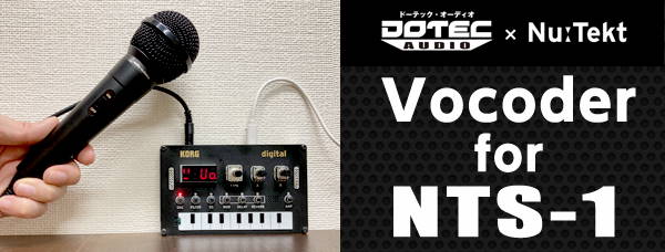
So, as for the vocoder we’ve developed, it’s a full-fledged 16-band vocoder.
Connect a mic (which we call a “modulator”) to the NTS-1, and make the oscillator sound while you vocalize to get a cool robotized voice.
How did you like that? Isn't it amazing how you can make a 16-band vocoder run on this compact digital synthesizer?
We made this happen by taking advantage of some hidden tricks offered by the specs of the NTS-1. It’s a little complicated, but I’ll explain about this here.
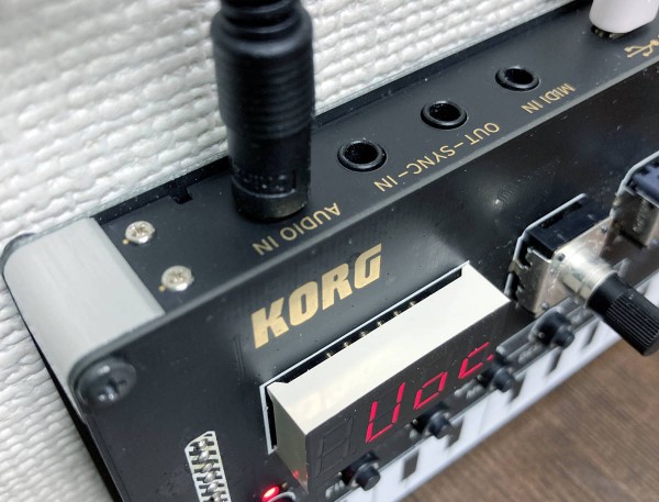
We can plug in a line-level audio input to this jack and apply effects or mix the oscillator sound with this input. (This is one of the fantastic specs that this unit offers.) However, the input needs to be line-level, and the input audio gets mixed with the oscillator sound, which are hurdles we had to figure out how to overcome.
- About the line input (audio input level)
Since the NTS-1 input requires line input, we would ordinarily need a mic amp or a mixer to amplify the sound if we wanted to plug in a mic.
Also, since this jack was designed for line input, this unit also features an attenuator that is necessary to attenuate the levels.
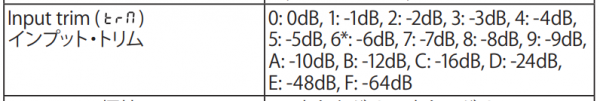
Luckily, the NTS-1 has “global parameter” settings, which can be used to change how various operations work on this unit.
I’d like you to refer to the “Global Parameters” section in the Owner’s Manual that comes with the NTS-1 (on the lower right-hand part of page 16). There’s a parameter called “Input Trim.”
If you can’t find it in your Owner’s Manual, please download the latest one
from here. It also might be necessary to update your NTS-1 via PC.
The factory default setting for this parameter is “6:-6DB”, but by setting this to “0:0DB” we can disable the attenuation. Use this setting when you want to plug in a dynamic mic or similar device without using an amp. (You don't need to make this setting for a line input device.)
If the input volume is still too low, we can overcome this by setting the vocoder parameter A to “Gain” and adjusting this knob to amplify the volume by 100 times maximum.
- About the input audio and oscillator sound
A vocoder uses the audio from a mic input (the “modulator”) to process the sound of a synthesizer (the “carrier”). Although both of these elements require separate inputs, the NTS-1 does not have this feature.
What happens is that the sounds of the synth and external input get mixed together and then processed by the effect. You can try it out and see what I mean.
To circumvent this, we came upon a bold idea to separate the sounds by using the differential in the stereo audio.
For example, if you have the same synthesizer sound in both the left and right channels, but then add the mic sound to just one channel, you’re able to extract the audio from the mic by using the differential from both signals. Does this line of reasoning make sense?
So, it can be shown as the following formula;
(mic signals + synth signals) – synth signals = mic signals
Using this method on the NTS-1, we separate the audio from the oscillator sound and process them to make our vocoder this time a reality!
That aside, we should note that there’s a little trick involved in connecting the mic, some examples of which are shown below. (Prerequisite: get the L channel as mic input)
- Use a monaural-output dynamic microphone - From the beginning, prepare a sound source where your voice is heard only on the L channel (R channel should be silent), and use line input to bring the stereo signal into the NTS-1 - Use the line input from a mixer to bring the stereo signal containing only the mic sound on the L channel into the NTS-1 - Use a splitter cable to connect the mic to only the L channel
-
Example of connection using a dynamic microphone

-
Example of connection using a splitter cable
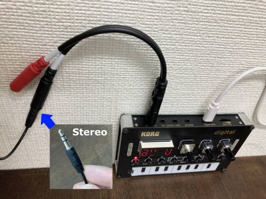
Using a monaural-output microphone is the simplest way. If you use a stereo-output microphone, you can get the same result with a splitter cable. Have a try!
With all that said, you can download a trial version of our vocoder together with the oscillator as a set for free. You can try it for 3 minutes in a trial version. And a full version is now sold for $10 (excluding tax) on the DOTEC-AUDIO website.
https://dotec-audio.com/nts1.html?lang=en
Frankly, I’m just blown away by the fact that we can use the NTS-1 as a vocoder.
Since you’re here, I’d like to give you a rundown of who we are at DOTEC-AUDIO as well as our original product lineup.
DOTEC-AUDIO is a software brand that’s managed and operated cooperatively by musician and engineer Frank Shigetora and by fmfmsoft Corp.
Our general business is the development and sales of plugins for music-related software like DAWs that operate on Windows, macOS and iOS (for some products).

The KORG Gadget2 includes a maximizer made by DOTEC-AUDIO called “DeeMax,” so you might have heard of us from that.
Six years have passed since DOTEC-AUDIO got started, and we now have a much larger lineup of products, including products for musicians doing music production on a PC and products for content distribution. If you’re interested, please check out our website. There are a few products there in particular that have a deep connection with what we’ve talked about in this article series.
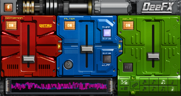
- DeeFX Multi-Effect
English website:
https://dotec-audio.com/deefx.html
We briefly touched on this product in the first article. This is a multi-effect that gives you standard distortion, filter and delay effects, but in a package that we’ve worked hard to fine-tune, making it super easy to use.
The design combines these three effects, which you can individually switch on and off and use as standalone effects processors.
Adding to this are bitcrusher and vinyl stop effects, which are simplified versions of what we featured in these article for use on the NTS-1.
This is a product that’s popular even with many pro musicians.
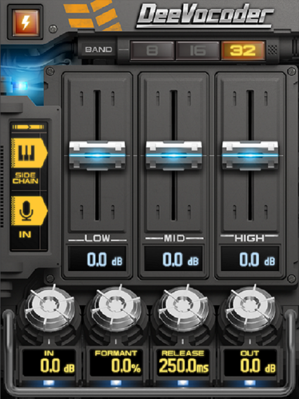
- “DeeVocoder” vocoder
English website:
https://www.dotec-audio.com/deevocoder.html
As the name suggests, this product is the vocoder made by DOTEC-AUDIO. This vocoder features a filter bank-type vocoder (which is now experiencing a revival) switchable between eight, 16 and 32 bands, as well as formant shift capabilities.
Unlike FFT-type products, our vocoder offers superior playability with no latency, giving you the power to create that impudent-sounding robot voice that’s normally created with analog vocoders.
We’ve placed emphasis on the positioning of this product as an effect, as by using this familiar synth plugin for sidechain input, the vocoder as a carrier opens you up to endless sonic creation possibilities. Of course, any audio input to the sidechain can be used as a carrier, so you can enjoy using this plugin effect at your whim for not only synth sounds but also guitar, bass guitar, drums and more.
In this way, since this is a plugin for use with DAWs, it offers a different kind of freedom from the vocoder that works with the NTS-1.
DOTEC-AUDIO products all feature a demo version that you can try for free (no need for user registration or other trouble). If you use software for plugins such as VSTs or audio units, we definitely hope you’ll try out our products!
This article series is part of a proposal that we made to KORG. The reason for doing this was that we wanted to talk about how the NTS-1 is such a massively appealing platform for programming.
What’s so fantastic about the NTS-1 is that its compact hardware and ability to program give you such a high degree of freedom.
Further, as audio programming pros we’re so excited about how the NTS-1 has an audio input and can be used as a synthesizer or as an effects unit. It’s really interesting how the NTS-1 offers all this, while still being eminently affordable. That’s why we proposed this article series—we wanted to tell as many people as possible about the fascination of this product.
As we’ve written over and over again, the basics of audio programming are the same, whether you’re using the NTS-1 or working with a DAW plugin.
Although there may be an infinite number of ways to make your solution work, it all comes down to how you want to build the sound you’re looking for, between the input and the output.
We hope that this article series has given an opportunity to as many users as possible to build an interest in understanding how their favorite music and synth apps are designed, while playing around with the NTS-1.
I’d like to offer a heartfelt thanks to everyone for reading along with this article series!
Also, my thanks to the people involved at KORG, who agreed to publish this series.
Hope to see all of you someday!
Frank and Iijima at DOTEC-AUDIO
NTS-1 digital kit
PROGRAMMABLE SYNTHESIZER KIT
Related Products
Copyright © 2024 KORG Inc. All Rights Reserved.
Choose Your Location ![]()